Section K (26/12/08 )
FUEL SYSTEM
K.1 General
K.2 Removal of the fuel tank
K.3 Removal of the fuel gauge float unit
K.4 Removal of the filter tube assembly
K.5 Removal of the fuel strainer
K.6 The fuel pump
K.7 Air cleaner
K.8 The carburettor (Stage I)
K.9 Description and operation
K.10 Carburettor adjustments
K.11 Overhauling the carburettor
K.12 The carburettor (Stage II)
K.13 Tuning and fitting instructions
K.14 Specifications and repair data
|
|
||
|
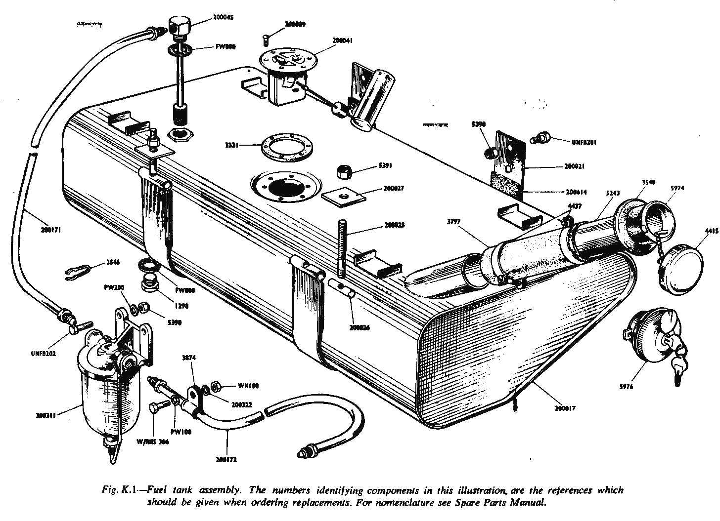
Kl The 81/2 gallon capacity fuel tank is situated at the rear of the chassis and is secured by straps to the rear of the chassis underside. Delivery of the fuel is effected by a mechanically driven pump drawing fuel from the tank through a filter tube assembly and flexible nylon pipe to a petrol strainer mounted on the engine bulkhead. Fuel content is measured by a float-operated variable resistance located in a well on the tank upper surface; the resistance is transmitted to the fuel contents gauge mounted on the facia panel. K2 Removal of the Fuel Tank Jack up the vehicle and drain off petrol at drain plug.
Disconnect tank inlet pipe from flexible hose by removing Jubilea clips
and disconnect fuel gauge wiring at the float unit; access to these items
is through the luggage boot, a small inspection plate being removed to
expose the float unit beneath. Unscrew the two nuts securing the strap
trunnions to the chassis cross member, collect the nuts and two retaining
plates. When the tank is removed, the straps can be left attached by their
bolts and nuts to the rear chassis cross member. K3 Removal of the Fuel Gauge Float Unit With the fuel gauge electrical wiring previously disconnected, remove six retaining screws and lift out float unit with cork gasket. Care must be exercised not to bend or strain the float lever or dent the float. When refitting the float unit, check that the cork gasket is clean and undamaged prior to coating with jointing compound. Position the float unit in the tank and secure with six screws ensuring that the joint between the tank and the fuel unit is fuel tight. K4 Removal of the Filter Tube Assembly Unscrew assembly from the tank, exercising care with filter end to prevent damage. Collect flbre washer. When refitting the assembly ensure that the fibre washer is clean and undamaged. Tighten down and secure to ensure a fuel tight joint. |
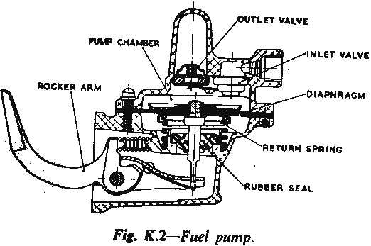
K5 Removal of the Fuel Strainer Disconnect fuel pipes from the tank and fuel pump at the fuel strainer, with nine fixing clips to the right hand side of the chassis. NOTE: Whenever fuel pipes are disconnected, the ends must be sealed to prevent the ingress of dirt or moisture. K6 THE FUEL PUMP The fuel pump is mounted on the right hand side of the engine, adjacent to the oil filter, and is driven by means of a rocker arm from an eccentric on the camshaft. Operation of the Fuel Pump On rotation of the engine, the eccentric on the
camshaft pivots the fuel pump rocker arm and link, and pulls the diaphragm
downwards against the pressure of the return spring. This creates a
partial vacuum in the pump chamber, causing the inlet valve to open and
draw fuel from the tank through the pipe line and the glass sediment bowl.
Any sediment in the fuel is deposited in the glass bowl, being filtered by
the gauze in the top of the sediment bowl before passing on to the fuel
pump.
|
|
|
During the time that the diaphragm is held down by fuel pressure, the rocker arm idles on the eccentric without operating the link. Cleaning the Fuel Filter Screen The glass sediment bowl and filter (mounted on the front bulkhead, Left Hand Drive only) should be removed and washed in petrol every 5,000 miles (8,000 km.). To Remove and Replace 1. Slacken off the clamp screw at the base of the sediment bowl, move the retainer clip aside and detach bowl, filter screen and cover gasket. 2. When replacing the filter screen, ensure that it seats in its housing correctly, and also that the cover gasket fitted between the sediment bowl and the body is in good condition, as an air leak at this point may cause failure of the fuel supply. If in doubt, fit a new cover gasket and tighten the clamp screw securely. 3. Complete removal of the sediment bowl can be effected by the removal of the two bolts and Oddie nuts securing the bowl to the bulkhead. NOTE : There is no sediment bowl on the R.H. Drive car and the fuel supply is fed direct from the tank to the AC fuel pump. Testing the Fuel Pump Provided there are no air leaks or obstructions in the fuel lines, a quick check on the pump can be made, as follows: 1. Disconnect the fuel pump from the carburettor pipe at the pump outlet or the carburettor union. 2. Crank the engine, using the starter motor, when there should be a well-defined surge of fuel for each revolution of the camshaft. If the pump does not operate correctly, check the inlet depression and delivery pressure, using suitable gauges. Fuel Pump Inlet Depression Test 1. Fill the float chamber with petrol. 2. Disconnect the fuel pump flexible pipe from the pump inlet and connect a vacuum gauge to the inlet union. 3. Start the engine and allow it to run at an idling speed, when the vacuum reading should be at least 10 in. (25,4 cm.) of mercury. 4. Stop the engine, when the gauge needle should take at least one minute to drop back to zero. Fuel Pump Delivery Pressure Test 1. Fill the float chamber with petrol. 2. Disconnect the fuel pump to carburettor pipe and connect the pressure gauge to the pump outlet. |
3. Start the engine and observe the pressure when running at idling speed. Momentarily race the engine and observe the pressure. This should not be less than 11 lb./sq. in. (0,10 kg./sq. cm.) and not more than 3 lb./sq. in. (0,21 kg./sq. cm.) at any speed. Fuel Pump Removal and Replacement To remove: 1. Disconnect the fuel inlet and outlet pipes. 2. Unscrew the two nuts securing the pump to the cylinder block and detach the pump. 3. Remove pump gasket. To replace : 1. Locate new gasket on pump mounting flange studs. 2. Refit the pump to the cylinder block studs, passing the rocker arm up between the camshaft eccentric and the wall of the crank case. Replace the two securing nuts and spring washers and tighten to 12 -> 15 Ib. ft. (1,66 -> 2,07 kg. nm.). 3. Reconnect the fuel inlet and outlet pipes to their respective unions on the pump and tighten securely. K7 AIR CLEANER To carry out normal servicing, remove the three
securing bolts and one nut. The cleaner can then be removed from the car.
Unscrew the, filter bowl, empty out the old oil, clean out thoroughly and
refill with fresh oil to the indicated level. Reassemble and fit to the
carburettor. |
|
|
K8 THE CARBURETTOR (STAGE I) The Stage I carburettor is of the single-venturi vertical downdraught type. It incorporates an accelerator pump to ensure rapid acceleration, an economy device controlled by manifold depression is incorporated in the carburettor body to improve petrol consumption at higher speeds, and a choke valve of the strangler type for cold starting. K9 DESCRIPTION AND OPERATION
|
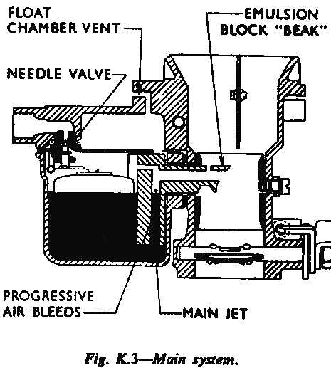
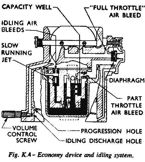
As the petrol level in the main jet channel falls, a number of small holes in the side of the channel are progressively exposed, see Figs. 3 and 4. This admits an increasing quantity of air into the system, thus maintaining the correctly balanced fuell-air ratio of the mixture. Economy Device (see Fig. 4) At the side of the carburettor body is a small casting attached by three screws. Inside is a diaphragm valve, which is normally held in a flexed condition by a compression spring. From the spring compartiment a small drilling gives direct communication with the engine side of the throttle plate through internal channels. Under 'part-throttle' cruising conditions, the manifold depression is high. This depresssion is imposed on the spring-loaded side of the diaphragm, thereby lifting the valve from its seat and so increasing the ventilation via the 'part-throttle' air bleed to the jets, thus weakening the mixture. When the depression in the manifold is low, the valve remains on its seating under the influence of the spring. The air supply to the jets is consequently limited to the permanent restriction of the 'full throttle' air bleed. The action of the economy device is entirely automatic and is controlled by the demands of the engine. Accelerator Pump System (see Fig. 5) The purpose of the accelerator pump is to prevent any hesitation when suddenly accelerating by providing a controlled and metered supply of fuel into the carburettor venturi coincident with the sudden opening of the throttle plate.
|
|

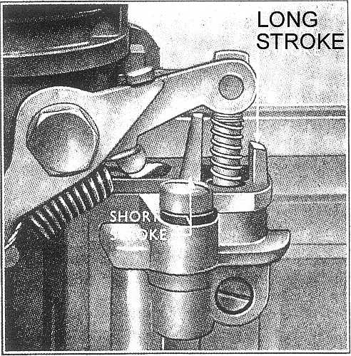
When the pump piston is at the top of its stroke, the pump chamber is charged with fuel admitted from the float chamber through the non-return valve at the base of the chamber. When the throttle is suddenly opened, the piston is forced down by the throttle linkage and discharges a stream of petrol through the nonreturn valve located at the top of the float chamber body, and through the horizontal discharge nozzle into the main air stream. The pump piston is returned to the charged position by the piston spring and is then ready for the next stroke. The travel of the piston, and consequently, the volume of fuel discharged at each stroke can be set in one of two positions. (See 'Carburettor Adjustments.") K10 CARBURETTOR ADJUSTMENTS (a) Slow Running Adjustment (see Fig. 6) |

When a suitable vacuum gauge is not available, the engine should be warmed up and the throttle stop screw turned clockwise so that the engine is running at a fast idling speed. Screw the volume control screw in or out until the engine runs evenly. Now readjust the throttle stop screw if the engine is running too fast, followed by a further readjustment of the volume control screw. These operations should be repeated until the idling speed is satisfactory. It may be necessary to readjust the ignition setting.
|
|
(b) Accelerator Pump Stroke Adjustment A felt seal is incorporated in the top carburettor body below the adjusting collar.
(c) Choke Adjustments The choke control cable is adjusted at the choke lever plate trunnion so that there is approximately 1 in. (3,18 mm.) free play in the cable when the control is pusbed in fully. The correct degree of throtthe opening when the choke plate is closed for starting is obtained by placing a 0,914 mm. drill (No. 64) between the edge of the throttle plate and the carburettor body at right angles to the throttle spindle. This setting can alternatively be obtained by screwing in the throttle stop screw approximately six turns from the position at which it just abuts the throttle plate stop when the throttle is fully closed (it will be necessary to remove the throttle stop screw spring for making this adjustment as the spring becomes 'coil-bound'). Then adjust the length of the choke link so that the choke lever plate is in the fully closed position.
|
(d) Float Adjustment To check the fuel level it is necessary to remove the float chamber. Operate the starter motor (ignition off) to fill the float chamber to its correct level. Remove the four bolts securing the float chamber to the carburettor body and carefully detach the float chamber. With the float in position the petrol level should be 7/8 in. (22,5 mm.) below the top face of the float chamber. If the float is removed, the petrol level will fall and should then be 1-5/16 in. (33 mm.) below the top face. If the petrol level is low the float arm should be bent upwards or bent downwards if the level is too high. After adjusting the float arm, refit the float chamber and re-check the petrol level as before. K11 OVERHAULING THE CARBURETTOR To Remove 1. Remove the air cleaner. 2. Disconnect the choke control cable at the choke lever plate and slacken the clamp on the choke cable abutment bracket. 3. Disconnect the throttle at the upper end of the throttle lever connecting rod. 4. Unscrew the fuel pipe union. 5. Disconnect the distributor vacuum pipe at the rubber connection on the right-hand side of the carburettor. 6. Unscrew the carburettor flange nuts and spring washers and remove the carburettor.
|
|
|
To Dismantle
To Reassemble 1. Refit the choke tube and secure it in place with the retaining screw. Ensure the end of the screw correctly locates in the hole in the choke tube, fully tighten the screw and bend one tab of the lockwasher to retain it in position. |
|
|
|
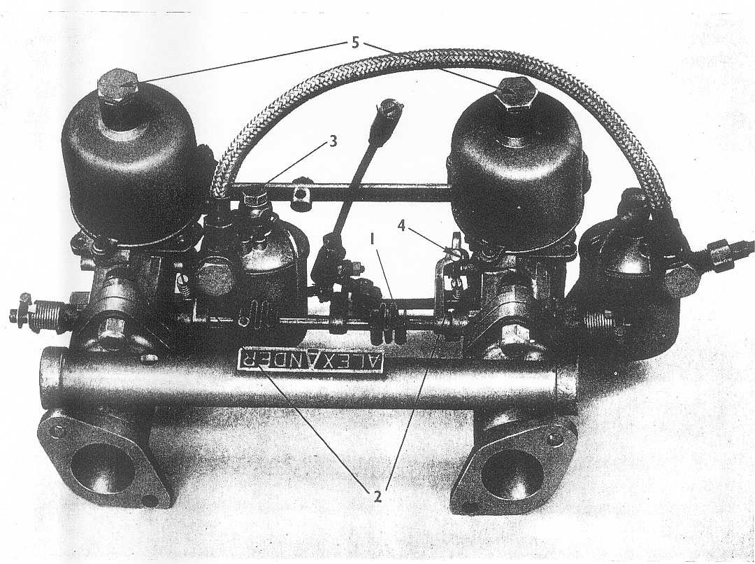
To Replace 1. Locate a new gasket on the manifold flange and replace the carburettor with the float chamber to the front. Refit the spring washers and nuts on the mounting studs and tighten them securely. 2. Reconnect the distributor vacuum pipe to the rubber connection on the right-hand side of the carburettor. 3. Refit the fuel pump pipe and tighten the union. 4. Refit the throttle control rod to the upper end of the throttle lever connecting rod. 5. Connect the choke control cable (at the rear of the carburettor) and tighten the clamp. Pass the cable inner wire through the choke lever plate trunnion and tighten the clamping screw. Check that the choke opens and closes correctly, and that there is slight play in the cable. 6. Refit the air cleaner. K12 THE CARBURETTORS (STAGE II) Conversion to give Stage II performance can be effected, calling for the substitution of twin S.U. Carburettors for the Single Zenith downdraught unit.
K13 TUNING Fitting Instructions (Twin Carburettor Assembly)
|
The S.U. carburettors are of the automatically expanding choke type, in which the size of the choke and the effective area of the jet vary according to the degree of throttle opening used against the prevailing load. This regulation of the choke size gives a fairly constant air velocity over the jet and ensures good atomisation, therefore multi-jets are unnecessary. The single jet used is varied in effective area by a tapered needle which moves up and down in the jet orifice. The profile of the needle is decided to suit each type of engine and running conditions. Multi-carburettor installations cannot be successfully tuned unless the general condition of the engine. i.c., compression, ignition system. are in a satisfactory state. With regard to the carburettors themselves, the cleanliness of the section piston units, the position of needles, the jet centering and oil level in the dampers should be checked. The following sequence of tuning should be followed:
|
|
|
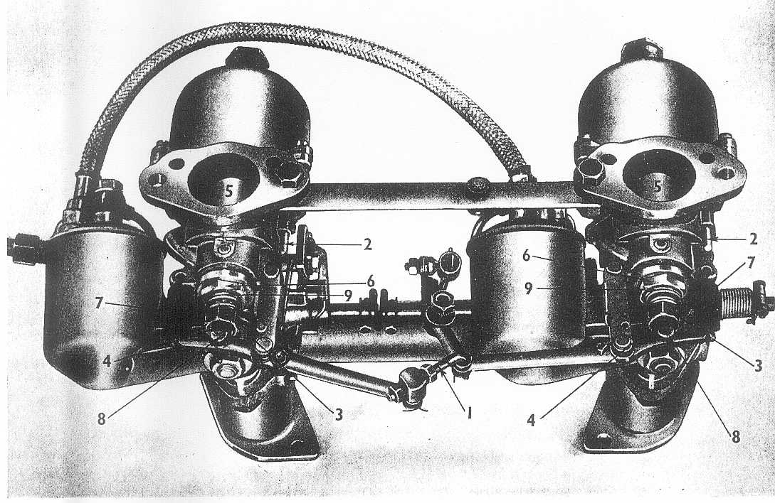
Jet Centralising When the piston (5) Fig. 10 is lifted by hand, with the engine not running and the jet adjusting nut screwed up fully, it should fall freely and come into contact with the jet bridge with a soft metallic click. If this does not happen, then repeat the test with the jet in its fully lowered position. If the click is now audible and the piston falls freely then the jet nut must be re-centralised with the needle. The jet nut which is clamped in position by the gland nut (6) Fig. 10 is located in a clearance bore which permits a limited amount of float when the gland nut is slackened. Therefore, it can be moved until it is concentric with the jet needle, allowing the piston to fall freely to its lower position. To re-centralise proceed as follows: 1. Remove the air filters. 2. Remove the return springs (7) and pivot pins (8) (Fig. 10). Move the linkage out of the way. 3. Remove piston dampers (5) Fig. 11. 4. Withdraw the jet (4) Fig. 10 and remove the adjusting nut (3) and springs (9). |
|
 |
||
Float Chamber Fuel Level The level of the fuel in the float chamber is governed |
by the action of the forked lever in the float chamber lid which acts upon the needle valve. The following procedure should be adopted if it is ever suspected that the fuel level is not correct. 1. Disconnect the fuel pipe and remove the float chamber lid securing bolt (3) Fig. 1 1. Lift off the lid. 2. With the lid inverted and the forked lever resting on the needle valve thus closing it, it should be possible to pass a 7/16 in. diameter (11->112 mm.) rod between the radius of the forked lever and the float chamber lid. If the forked lever fails to conform witbin 1/32 in. (0,7937 mm.) of the check figure, bend it carefully at the start of the fork section, but take care to keep both prongs parallel with each other. There should be no need to alter the fuel level unless flooding is experienced. This can be caused by grit jamming the needle valve, a punctured float or excessive engine vibration; these points should be checked first. 3. Re-assemble. |
|
 |
||
|
K14 SPECIFICATIONS AND REPAIR DATA Fuel Tank Location... ... ... ... ... ... ..... ... ... ... ... At rear of car, under luggage boot floor Capacity... ... ... ... ... ... ... ... . ... ... ... 81 Imp. galls. approx. (10,2 U.S. galls., 45,4 litres) Fuel Pump Type... ... ... ... ... . ... ... ..... ... .Diaphragm, operated by eccentric on camshaft Delivery Pressure... ... ... ... ... . ... ... ... 2 to 3-1/2 Ib/sq. in. (140,6 to 246,05 gm/sq. cm.) Inlet depression ... ... ... ... ..... . ... ... ... ... ... ... ... ... ... ...... ..10 in. (25,4 cm.) of mercury Fuel Pump Diaphragm spring: Test length... ... ... ... ... ... ...... . ... ... ... ... ... ... ... ... ... ... ... ... ... ...19/32 in. (15,081 min.) Test load .. ... ... ... ... ... ... .. ..... ... ... ... ... ... ... ... ..104 to 112 oz. (2,949 to 3,175 kg. m.) Rocker arm spring: Test length ... ... ... ... ... ... .. ..... ... ... ... ... ... ... ...... ... ... ... ... ... ... 23/32 in. (18,256 mm.) Test load ... ... ... ... ... ... ...... ... ... ... ... ... ... ... ... ... ...164 to 172 oz. (4,65 to 4,88 kg. m.)
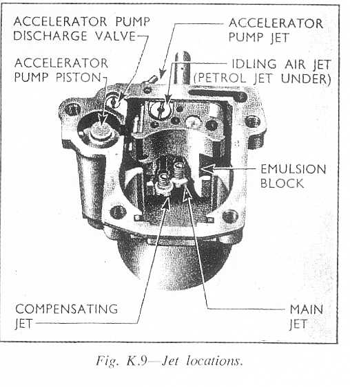
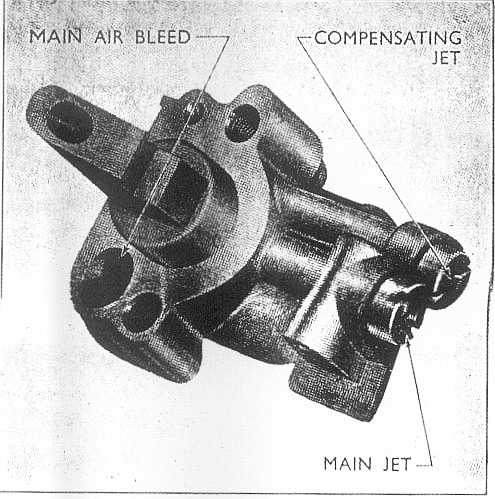
Carburettor (Stage I) Type ... ... ... ... ... ... ... ... .. .... ... ... ... ... ... ... ... ... ... ... Zenith, single-venturi downdraught Main jet ... ... ... ... ... ... ... .. ... ... ... ... ... ... ... ... ... ... ... ... ... ... .. . ... ... ... ... ... ...... ... ... 95 Main air bleed ... ... ... ... ... .. .. ... ... ... ... ... ... ... ... ... ... ... ... ... .. . ... ... ... ... ... ... 1,8 mm. Idling jet ... ... ... ... ... ... ... .. .. ... ... ... ... ... ... ... ... ... ... ... ... ... ... ... ... ... ... ... ... ... ... ... 45 Compensating jet ... ... ... ... .. . ... ... ... ... ... ... ... ... ... ... ... ... ... ... . .. ... ... ... ... ... ... ... .105 Accelerator pump jet ... ... .. ...... ... ... ... ... ... ... ... ... ... ... ... ... ... ... ... ... ... ... ... ... ... ... 50 Idling jet air bleed ... ... ... ...... .. ... ... ... ... ... ... ... ... ... ... ... ... ... ... .. . ... ... ... ... ... ... ... 70 Choke tube diameter ... ... .. .... ... ... ... ... ... ... ... ... ... ... ... ... ... ... ... ... ... ... ... ... ... 28 mm. Needle valve ... ... ... ... ... .. ... ... ... ... ... ... ... ... ... ... ... ..... ... ... ... ... ... ... ... ... ... . 1,75 mm. Float chamber level: Float in ... ... ... ... ... ... ...... ... ... ... ... ... ... ... ... ... ... ... ... ..7/8 in. (22,5 mm.) below top face Float out ... ... ... ... ... .. ... ... ... ... ... ... ... ... ... ... ... ... ..1-5/16 in. (33,5 mm.) below top face
Carburettor (Stage II) Type ... ... ... ..... ... ... ... ... ... ... ...... ... ... ... ... ... ... ... ... ... .. ... ... ... ... ... ... Twin 1/2 H4 S.U. Main jet ... .. ... ... ... ... ... ... ... ... ... ... ... ... ... ... ... .... ... ... ... ... ... ... ... ... ... ... ... ... ... ... ...90 Needle valve ... ... ... ... ... ... ... ... ... ... ... ... ... ... ... ... ... ..G.S. Needle and red damper spring |
||