Section Q (26/12/08 )
BODYWORK
Q.1 General
Q.2 Brackets and fixing points
|
|
||
|
|
||
|
Ql There are three types of body styling: the Soft
Top, with Vinide hood, the Hard Top, with fibreglass reinforced plastic
moulded roof, and the Gran Turismo, which has a fixed roof, extending in a
continuous sweep, to the rear of the car. Soft Top and Hard Top versions have rear boots, with
front-hinged, moulded boot lids and stays. The Gran Turismo bas no
separate boot compartment, but has access to the same rear storage space
from within the car. Both Soft Top hoods and Hard Top roofs are secured to
the top of the windscreen with three toggle-catches, and to the body with
inside rear catches. The Soft Top hood and frame folds to stow behind the
seating positions, with a hood envelope to enclose it. The Hard Top roof
can he removed completely for open touring. The Hard Top roof moulding is
exclusive to that version of the car. Both the Hard Top and Soft Top
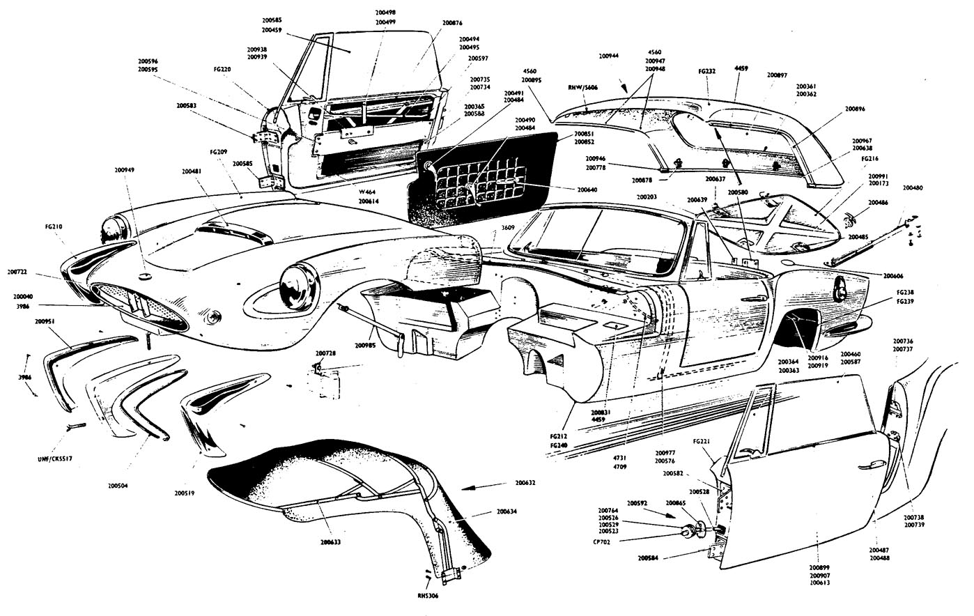
versions have the moulded, front-hinged boot lid. The bodies of the three versions are constructed with
the following seven fibreglass reinforced plastic moulded panels.
Bonnet, boot and door moulding rebates are trimmed with
foam rubber in the rebates, for anti-vibration and the exclusion of water
and draughts, as appropriate to their function. Q2 THE MAIN BODY The main body is of one-piece fibreglass construction
with integral bonding of wood flooring and tubular steel bracing. |
This assembly includes the scuttle, seat wells, doorways, rear bulk head, luggage boot and rear
mudguards. The rear bumpers are moulded into the rear section
of the main body and are clad with chromium-plated steel pressings.
The main body, which rests on felt strips, is
attached to support brackets at the forward end of the chassis.
immediately behind the front wheels, by four 5/16 in.
U.N.F. by 3/4 in. long hex. high tensile steel fixing screws,
four 5/16 in. i.d. plant steel washers and four 5/16 in. U.N.F.
hex. self-locking nuts. Two of each passing from the wheel-well through
the forward body mounting brackets, which are welded to the chassis, and
the bodywork, to be secured from within the cockpit footwells. Under the
door sills, on either side, two high-tensile steel 1/4 in. U.N.F. by 1-1/8
in. long hex. bolts pass through the wooden floor panels and the main
longitudinal chassis members to be secured by
two 1/4 in. U.N.F. hex. self-locking nuts with 1/4 in. i.d. plain
steel washers. The rear body is secured to the chassis on
either side by four 5/16 in. U.N.F. by 3/4
in. long hex. high-tensile steel fixing screws, four 5/16 in. i.d.
plain steel washers and four 5/16 in. U.N.F. hex. self-locking nuts, the
bolts passing through drilled angles on the rear body behind the rear
wheels to pick up on holes drilled in the rear chassis
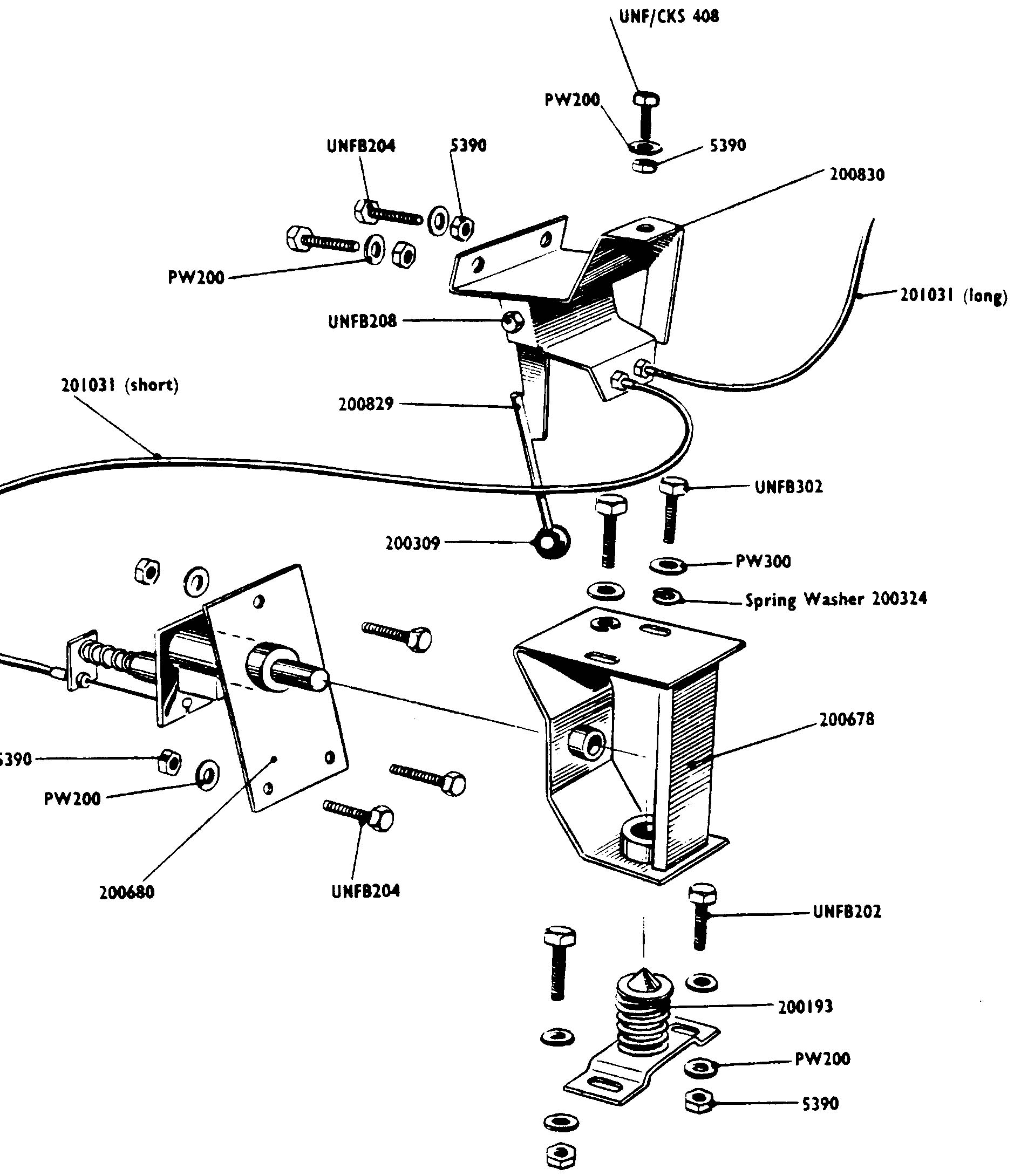
members. The bracket securing the handbrake lever is retained by
two 5/16 in. bolts, which pass through the floor boards and chassis and
form another body-to-chassis attachment, two 5/16 in. i.d. washers and two
5/16 in. hex. self-locking nuts.
The inboard seat channels are secured
in a similar manner, their 1/4 in. U.N.F. retaining bolts (four to
each rail) passing through floor and chassis to be secured by 1/4 in. i.d.
plain wasbers and 1/4 in. U.N.F. hex. nuts. The main body is moulded at the forward end to follow
the contour of the wheel-well and is recessed to house the
battery on the right hand side and the carburettor linkage on the
left. Rubber edged fibreglass splash guards are fitted to the front
wheel-wells and these are attached by Spire speed screws to the upswept
chassis member and to the main body work. These guards conceal and protect
the front body-to-chassis
attachment bolts. Above the footwells a sloping shelf carries the fuse box
and junction boxes, also the
clutch fluid reservoir (left hand drive car only).
The shelf also carries the windscreen wiper motor. The
bulkhead below the scuttle is drilled to accommodate control cable
and wiring grommets and carries a rubber sealing strip on which the closed
bonnet rests. This strip is also fitted to the rebates outboard of the
sloping shelf on either side of the car. The scuttle is reinforced by a tubular steel former
which is secured to both the body moulding and the flooring throughout its
length. The steel bracketry to which the pendant footpedals are attached
is bolted to the body work below
the scuttle. At the rear the main body is recessed to accomodate the
fuel tank filler cap, behind and above the lefthand rear wheel, and at the
extreme rear it is shaped and drilled to carry the registration plate. |
|
|
The space between the separate floor pannels is bridged
by a gearbox cover and a prop-shaft cover, both of which are moulded in
fibreglass. The gearbox cover is secured by 14 Spire Speed fixing screws,
Spire Speed washers (3/16 in. i.d. plain) and Spire Speed nuts. A Clayton
Wright 'Stick-a-Strip seal is fitted to ensure draught and fume exclusion.
The prop-shaft cover is retained by 12 No. 8 by 1/2 in.
long chromium plated, recessed head fixing screws. A gear lever cover, of
moulded rubber, is fitted to the prop-shaft cover where this is cut out to
accommodate the gear lever. The luggage boot is floored by a ribbed fibreglass
moulding which rests on the rear chassis members and provides a cover for
the underslung fuel tank. A circular hole in the boot floor provides
access to the tank unit and this is covered by an 18 S.W.G. aluminium
pannel, 4-1/2 in. in diameter, secured by two No. 8 by 3/8 in. long type A
Phillips screws. Within the rear wheel arches are mud flaps moulded from
fibreglass to the contour of the rear wings. The mud-flaps, being handed,
are not interchangable and are attached to either side by two 1/4 in.
U.N.F. by 3/4 in long fixing screws and one 1/4 in U.N.F. by 7/8 in. long
fixing screws, each of which has two 1/4 in. i.d. plain steel washers and
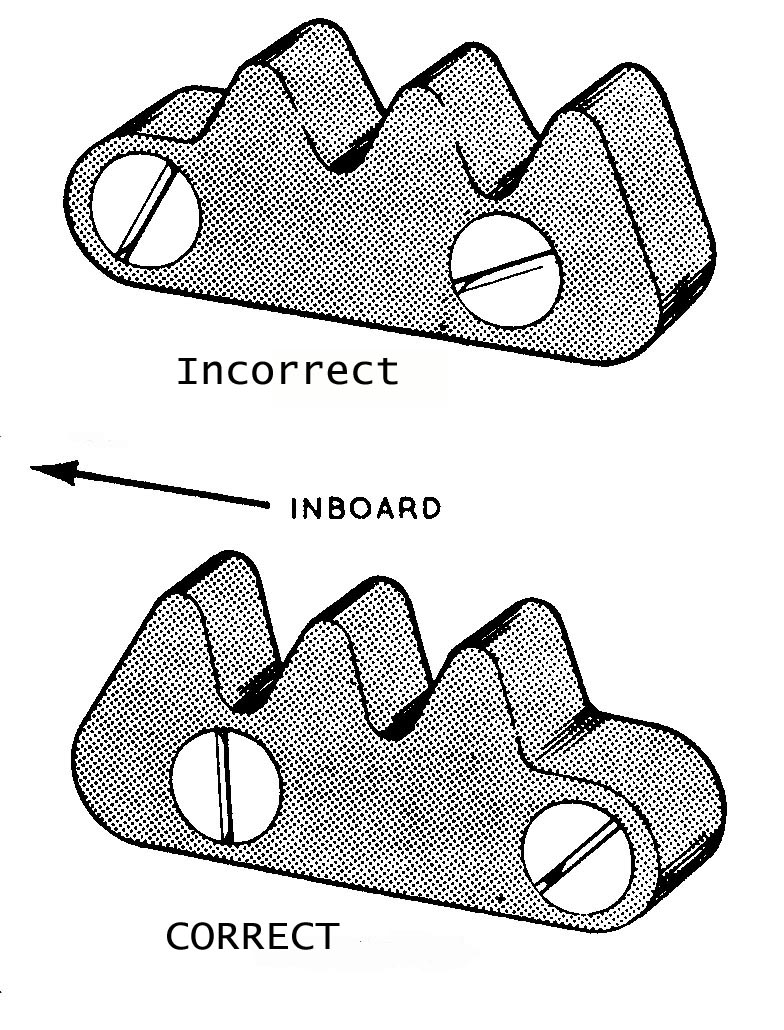
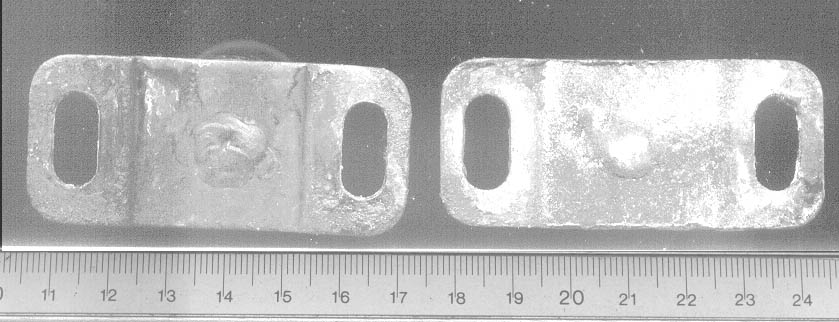
a 1/4 in. U.N.F. hex. self-locking nut. The door lock strikers are attached to the main bodywork and each of these assemblies is secured by four 10 U.N.F. by 1-1/4 in. long countersunk screws. which pass through the striker and the fibreglass bodywork to be secured from within the wheel area by four 10 U.N.F. hex. self-locking nuts with four 3/16 in. i.d. plain washers. The striker rack, which is positioned below the striker on each
|
side, is secured by four 1/4 in. U.N.F. by 1-1/4 in.
long countersunk screws, four 1/4 in. i.d. plain washers and four 1/4 in.
U.N.F. hex. self-locking nuts. It is important that the striker rack,
which is not symmetrical, should be positioned as shown in fig Q2 and not
reversed. Q3 REMOVAL OF THE MAIN BODY The car has been designed to afford ease of maintenance
and servicing with a minimum of dismantling, and it will not be found
necessary to remove the main body for any reason other than a complete
rebuild. Access to gearbox
and prop-shaft may be gained by the removal of the seats and the
bulkbead trim which is secured by seven countersunk 3/16 in. Whitworth
fixing screws, two 1 in. three 3/4 in. long, each with a cup washer, plain
washer, spring washer and 3/16 in. fixing nut. Remove the two No. 8 by 3/4
in. long Phillips screws and lift off the ashtray. Withdraw
the rubber moulding from around the gear lever, unscrewing the knob
of the gear lever to permit the easy removal of the moulding. Remove the
front bulkhead trim carpet and the propshaft-cover-carpet, which are
retained by Carr carpet fasteners, and undo the screws holding the
fibreglass covers. The access provided by the removal of these
covers will be sufficient to permit work to be done on
the gearbox, prop-shaft and brake cable. Q4 THE BONNET (The Hood) The forward-hinging bonnet (hood) assembly is a
one-piece structure comprising engine bonnet and front wings. It is
rigidly constructed of reinforced fibreglass, its shape having been
designed to combine strength with appearance.
This major assembly carries the over-riders, front grille, parking
lamp and headlamp sub-assemblies. The bonnet
pivots on two hinges positioned on the undersides of the
forward ends of the longitudinal chassis members, and it is secured
on either hinge by a 2 in. hex. bolt. one plain
steel washer, one 18 S.W.G. special (brass) washer and one 1-1/4
in. o.d. 17/16 in. i.d. by 1/4 in. rubber washer and a selflocking 3/8 in.
U.N.F.
steel hex. nut. The
pivot bolts pass from the
outsides of the hinges having the plain steel washers under their heads
and the rubber washer sandwiched between the plain washer and the steel
angles on the bonnet stiffening members. The brass washer is fitted
as a shim between the chassis brackets and the bonnet angles. In
the closed position the bonnet is secured by a plunger operated release
mechanism mounted on each side of
the scuttle. The striker assemblies on the bonnet engage the spring
loaded, cable controled plungers and secure the bonnet when closed. When
in the locked position the bonnet holds two spring loaded lift plungers in
compression, and when the locking plungers have been withdrawn the lift
plungers react to raise the bonnet from its seating
|
|
|
on the scuttle, permitting a handhold for further
raising. In the raised, or
fully open, position the bonnet permits easy access to the engine,
steering and front suspension of the car and it is held in a near vertical
position by an angle section support arm. Q5 REMOVAL OF THE BONNET To remove the bonnet first disconnect the color-coded
wiring harnesses at the disconnect points adjacent to the front horns.
The horns themselves need not be disconnected. Removal of the hinge
bolts and dettachment of the support arm will permit the bonnet to be
lifted clear of the car, but during this operation its weight should be
supported to avoid undue loads or twisting on the hinges. Q6 THE DOORS Each of the two doors is a fabrication comprising two
reinforced fibreglass inner and outer mouldings. The doors carry the side
windows and their winding mechanisms, also the pivot ventilating window
assemblies. The doors are hung on their leading edges by two strong
hinges, each secured by four 1/4 in. by 1 in. long countersunk screws,
four 1/4 in. i.d. plain steel washers and four 1/4 in. U.N.F. hex.
self-locking nuts. Each hinge is attached to the main body by four 1/4 in.
U.N.F. by 1-1/4 in long countersunk screws, four 1/4 in. i.d. plain
washers and four 1/4 in. U.N.F. hex. self-locking nuts. These hinges are
not interchangeable. Each door is fastened by a Wilmot Breeden rotary lock,
these, being handed, are not interchangeable. The rotary lock is attached
and secured by two 10 U.N.F. by 3/4 in. long countersunk screws, two 3/16
in. i.d. plain washers and two 10 U.N.F. hex. self-locking nuts, to the
rear face of the door, and the star-wheel of this mechanisme engages with
the striker rack attached to the main car body when the door is closed.
From the outside, the door catch is freed by pressure on the push button
release embodied in the handle, and from within, by a remote control
handle located near the top leading edge of the door interior trim panel.
Movement of this handle actuates the lock via the remote control mechanism
and a pressed steel link located behind the trim panel, which connects the
remote control rod to the rotary lock. The remote control mechanism is
secured to the door structure by three 10 U.N.F. by 1 in. long countersunk
screws and to the lock by a 3/16 in. dia. by 1/2 in. long steel rivet and
a Spire Speed nut, and to the link by a pin. Two spring steel waved
washers and one special washer are used in the link-to-lock attachment. A pivot ventilating assembly is supported by each door,
the frame strip being secured to the forward, or leading edge of the door
by two 10 U.N.F. by 5/8 in.
countersunk screws |
two 3/16 in. i.d. plain washers and two 10 U.N.F. hex.
self-locking nuts. The rear channel attachment of the vent is made by an
angle bracket which, riveted to the channel, is secured through a hardwood
packing block to the inner moulding by a 1/4 in. U.N.F. by 3/4 in. long
hex. screw, a 1/4 in. i.d. plain steel washer and a 1/4 in. U.N.F. hex.
self-locking nut. Each pivot vent which is seated on a moulded rubber
seal, has two threaded studs, or shanks, built into its base and these
pass through the top of the door moulding to be secured by two special 1/4
in U.N.F. by 7/8 in.
long hex. nuts. Across the cut-away inner moulding of the door is
fitted the regulator channel, an 18 S.W.G. mild steel pressing, which
supports the drop glass stop subassembly and the door pull handle mounting
brackets, which are attached, respectively, by two 10 U.N.F. by 5/8 in.
long countersunk screws with : 3/16 in. i.d. plain washers and 10 U.N.F.
selflocking nuts and two 3/16 in. Whitworth by 3/4 in. long
countersunk screws with 3/16 in. plain wasbers and
3/16 in Whitworth hex. nuts. The drop glass assembly in the soft top version of the
car differs from that of the hard top but the fixture of both assemblies
is similar, the tempered sheet glass being held in a channel which is
attached to the regulator and the regulator
being secured to the door by six 1/4 in. U.N.F. by 3/4 in. long
countersunk screws. The glass stop sub-assembly is a 12 S.W.G. mild steel
pressing retained by the two Whitworth countersunk screws which pass
through the overlap of the glass stop sub-assembly before picking up the
two holes in the regulator channels. The door glass stop is a 2 in. by 1 in. by 3/8 in.
hardwood block surmounted by a 2 in. by 3/16, in. by 4 in. felt strip.
Each window is located by a glass channel which is secured to the door by
two 1/4 in. U.N.F. by 1-1/4 in. long countersunk
screws, two 1/4, in. i.d. plain washers and two 1/4 in. U.N.F. hex.
self-locking nuts. Three hardwood packing blocks, each 2 in. by 2 in. by
1/2 in. ensure the accurate positioning of the channel. The slot between the tops of the outer and inner door
housing through which the window slides, is faced on both its inner edges
by a 24 in. length of Silent Channel Weather Strip attached to each outer
moulding by eight Tucker Eyelets (TAP/D/BH 537) and to each inner trim
panel by eight Tucker Eyetets (TAP/D/BH 429). A chromium plated 22 S.W.G.
brass pressing is attached to the outer Weatber Strip, and to the door, as
an embellishment. Across the top of the inner door moulding cut-out is
fixed a 5/16 in. diameter casing board stiffener, this being secured at
either end by four rivets (TAP/D/BH 537).
The casing board stiffener support bracket is attached to the stiffener and to the glass slop sub-assembly by two rivets of
the same type. To prevent damage to
hinges and bodywork by the opening of a door beyond its normal pivot
angle, a strong check link has been fitted. |
|
|
This is located in the lower leading edge of the door
and it consists of a check link (a 10 S.W.G. mild steel pressing) attached
by a 14 S.W.G. mild steel lug to the interior of the door. The check link
passes through a slot in an oval slide plate which is attached to the main
body by two 3/16 in. Whitworth by 1 in. long countersunk screws, two 3/16
in. i.d. rectangular spring washers, two 3/16 in. i.d. plain washers and
two 3/16 in. Whitworth hex. nuts. A metal washer (13 S.W.G. mild steel)
and a rubber moulding are fitted to the check link behind the slide plate,
i.e. within the main body shell, to form a resilient door stop. The washer
and rubber moulding are retained by a 3/8 in. by 1/2 in. steel split-pin. The door is finished on the inside by a trim panel to
which are attached the escutcheons for the glass regulator and remote
control door handle. Through this trim panel pass the shafts to carry both
handles also the 10 U.N.F. by 3/4 in. fixing screws of the door
pull-handle, which pick up on the mounting bracket holes behind. Q7 REMOVAL OF THE DOORS Removal is effected by the detachment of the check link
slide plate and the withdrawal of the link from the main body, followed by
the withdrawal of the eight U.N.F. 1/4 in. by 1 in. long countersunk
screws, washers and nuts retaining the hinges, described earlier. Further
dismantling requires the removal of interior handles and the escutcheons
and the rim panel. This will provide access to the assemblies described
earlier. Q8 THE
BOOT LID (Trunk-lid) Moulded in reinforced fibreglass, the boot-lid consists
of an outer and an inner moulding which combine to form a most robust,
diagonally braced, shell. The boot-lid hinges upwards on two chromium
plated hinges to which it is attached by means of six 1/4 in. by l-3/8 in.
studs, and six 1/4 in. U.N.F. self-locking nuts. The boot-lid hinge bodies each have a 5/16 in. threaded
shank which passes through the bodywork to be secured by a 5/16 in. plain
nut and a plain washer. Gaskets are used on the assemblies and should not
be overlooked when dismantling and reassembling. The boot-lid is
supported, when raised, by a telescopic stay which is attached to the
right-hand edge of the lid inner moulding by two 1/4 in. U.N.F. by 1/2 in.
hex. fixing screws and two 1/4 in. i.d. rectangular spring washers. The
bottom of the stay is attached to a Z section bracket by two 5/16 in.
U.N.F. by 3/4 in. hex. fixing screws, a 5/16 in. i.d. plain washer and a
5/16 in. U.N.F. self-locking nut. The Z section bracket is itself attached
to the main body inner moulding. The boot lid is fitted with a Wilmot
Breeden lock, attached to an angled mounting plate by four 1/4 in. U.N.F.
5/8 in. long countersunk screws and four 1/4 in. U.N.F. hex.
self-locking nuts. |
Q9 REMOVAL OF THE BOOT-LID (Trunk-lid) The removal of the 5/16 in. nut. washer and screw at
the bottom of the boot lid stay and the detachment of the nuts and washers
from the studs securing the hinges will free the boot lid from the body.
There are no electrical leads to disconnect. Q10 WINDSCREEN There are two windscreens available for the car; one of
1/4 in. thick toughened glass and the other of 1/4 in. thick
laminated glass. Both are retained in the reinforced fibreglass
windscreen by an extruded rubber weather strip and a metal and plastic
filler strip. The windscreen is surmounted on the inside by a cloth
covered trim rubber on which
are mounted the hood fixing brackets, these being attached by two 10
U.N.C. by 1 in. long countersunk screws which pass through the rubber to
the frame. The two outer hood fixing brackets are of slightly different
shape to the centre bracket, but all three are castings of L.M.4
aluminium. Around the top of the windscreen frame runs the hood sealing
channel which carries the extruded 3 ft. 6 in. long. rubber hood seal.
This sub-assembly being retained
by 12 rivets (TAP/D/BH 429). Down each side of the windscreen run
aluminium water channels 14-1/2 in. long. each of which is secured by four
rivets (TAP/D/BH 429). On the rearward turned edges of the 'wrap-around'
windscreen frame are sealing rubbers 21 in. long. The windscreen frame
employs a tensioner stay which passes through a hole in the hood sealing
channel and again through a
hole in the facia below, to be secured and locked by two 1/8 in. Whitworth
hex. nuts. A rubber grommet is fitted to the facia hole through which the
tensioner passes. The windscreen frame is seated on a 56 in. rubber seal
and it is secured to the scuttle by five 1/4 in. U.N.F. by 1-1/4 in. long
hex. high-tensile steel bolts, two 1/4 in. U.N.F. by 1-1/4 in. long
countersunk screws, twelve 1/4 in. i.d. plain steel washers and seven 1/4
in. U.N.F. self-locking hex. nuts.
Q11 REMOVAL OF THE WINDSCREEN To remove the entire windscreen assembly it is first
neccessary to remove the tensioner stay by undoing the two nuts on the
underside of the facia and withdrawing the stay upwards from the hood
sealing channel. It is necessary to detach the facia from its seating to
permit access to the five 1/4 in. bolts and two 1/4 in. screws holding the
windscreen to the scuttle. The withdrawal of these will free the
windscreen completely but care should be taken not to damage the rubber
seals in the process, and for this purpose the car doors should be opened
wide before commencing work. |
|
|
Q12 THE FACIA The facia, or dash panel, is a matt-black reinforced
fibre glass moulding stiffened by a 1/2 in. by 16 S.W.G. by 36 in. long
mild steel stiffener. It is shaped to fit over the scuttle coaming and the
windscreen frame attachment flange, concealing the windscreen attachment
bolts and screws. It is secured on its right and left hand edges by two
1/4 in. U.N.F. by 3/4 in. and two 1/4 in. U.N.F. by 1-1/4 in. long
mushroom head screws, which pass from the cockpit side through the facia
and the scuttle behind, to be retained by four 1/4 in. i.d. plain washers
and four 1/4 in. U.N.F. hex. self-locking nuts. Q13 REMOVAL OF THE FACIA Before removing the facia from its mounting it will be
necessary to remove the windscreen tensioner stay and windscreen trim
rubber (see Windscreen) also the interior mirror, which is attached by
three No. 8 by 1-1/2 in. long wood screws. Remove the two 3/16 in.
Whitworth by 2 in. long countersunk screws and endplates securing the
crash roll. Remove the four mushroom head fixing screws which secure the
facia. Remove the grab-handle by removing the nuts and spacers referred to
earlier. Remove the steering wheel and boss (see Steering Section). Remove
the four raised head fixing screws holding the heater and demister
escutcheons. If the facia is to be detached completely, it will be
necessary to remove all instruments and controls mounted on the panel (see
Instrument Section). Behind the facia is a 12 S.W.G. mild steel bracket
which supports passenger's grab-handle and this must be detached from the
facia or from the scuttle before removal of the facia is attempted. The
removal of the four mushroom head screws, washers and nuts, described
earlier, will free the facia from its mounting. The eight screws, washers, and nuts securing the hood
frame attachment plates to the body should be withdrawn to free the
assembly from the main body. The assistance of a helper or the use of
props is recommended during the last stage of the detachment procedure to
prevent the frame structure from falling and possibly damaging the trim of
the car. Q14 THE HARD-TOP A hard-top assembly is available for the car, being
constructed in the same manner as the main body, i.e. of moulded
reinforced fibreglass, being located on, and secured to the main body by
four toggle fasteners each of which is attached by aluminium rivets
(TAP/D/BH 537). The clips for these fasteners are attached to the main
body on the cockpit sides and rear bulkhead, each by two No. 8 by 3/4 in.
long countersunk screws and two fixing nuts. |
Around the base of the hard-top is fitted a rubber
seal, 9 ft. 6 in. long, which is attached by 12 aluminium rivets (TAP/D/BH
537) with : 3/16 in. i.d. steel washers. A
large rear window is incorporated in the hard-top assembly and is retained
by a 9 ft. 6 in. rubber Weather Strip, locked by a filler strip of the
same length. On either side of the hard-top are 16 S.W.G. aluminium water
drain channels each attached by 10 aluminium rivets (TAP/D/BH 537). Q15 THE HOOD (Soft Top) The Vynide hood (soft top) canopy is supported by a
collapsible hood frame constructed of steel and designed to fold into a
storage envelope which, when not in use, is carried in the luggage boot.
When stowed, the folded hood - frame and canopy fits the contour of the
rear bulkhead and the storage envelope is then fitted to encase the
assembly, picking up on the ten Lift-the-Dot studs and two turnbuttons
which secure the hood canopy. The hood frame is attached to the main body on either
side by four 3/16 in. Whitworth by 3/4 in. long round head screws with
four 3/16 in. i.d. plain steel washers, the screws passing through the two
drilled plates on the canopy frame to pick up four holes on each side of
the main body, behind the doors and close to the coaming. They are secured
from between the inner and outer body mouldings by four 3/16 in.
rectangular section spring washers and four 3/16 in. Whitworth hex. nuts. Q16 REMOVAL OF THE HOOD When detaching the canopy from the main body, the hood
should first be released from the windscreen. The turn-button fasteners
undone, and the ten Lift-the-Dot sockets prised free.
Q17 INTERIOR TRIM All versions are fitted with two foam cushioned 'aero
style' folding seats, adjustable for fore and aft positions. There is room
behind the front seats for occasional seats, or for parcel and luggage
stowage to supplement boot space.
The cockpit floor panels and footwells are carpeted by four
tailored and bound felt carpets which abut the gearbox cover and
prop-shaft cover carpets on either side of the panelling, thirty Carr
carpet fasteners being employed to attach the carpet to the floor and
bulkhead panelling. An unfelted foot carpet of four square feet area is
also fitted. The
carpeting in the passenger's footwell is cut away in the vicinity of a
foot rest tube which, retained by two 1/4 in. |
|
|
U.N.F. by 3/4 in. long hex. bolts. two 1/4 in. i.d.
plain washers and two 1/4 in. hex self-locking nuts, is mounted on the
wooden floor panel. The two seats slide forwards and rearwards on four
runners each of which is attached by four 1/4 in. U.N.F. by 1-1/4 in. long
hex. high tensile steel bolts, sixteen 1/4 in. i.d. plain washers and
sixteen 1/4 in. U.N.F. hex. self-locking
nuts (the inboard runners are also secured to the chassis members, as described in the main body section). The front quarter casing trim on each side of the car
carries a map pocket and is attached by live No. 8 by 1/2 in. long fixing
screws and two 1/8 in. rivets. A door draft excluder is riveted by seven
1/8 in. rivets (TAP/D/BH 429) to each door and each excluder has a 2 in.
wide by 20 S.W.G. chromiuni plated end-cap. The door step edgings are pressings of 20 S.W.G.
polished aluminium, attached to the door sills on either side by live
rivets (TAP/D/BH 537). To the facia, or dash panel, is fitted a crash roll
moulding of reinforced fibreglass, this being secured by two 3/16 in.
Whitworth by 2 in. long countersunk screws and two endplates. On
the passenger's side of the facia a grab-handle is mounted, supported from
behind by a 12 S.W.G. mild steel bracket. The handle is itself secured by
two 1/4 in. U.N.F. hex. self-locking nuts with two spacers. The padded rear bulkbead trim. mentioned in the Main
Body Section, is held by two 3/16 in. Whitworth by 2 in. long countersunk
screws, two 3/16 in. Whitworth by 1 in. long countersunk screws, and three
3/16 in. Whitworth by 3/4 in. long countersunk screws each of which has a
cup washer, a 3/16 in. i.d. plain fixing washer, a 3/16 in. i.d.
rectangular section fixing washer and a 3/16 in.
Whitworth hex. nut. The screws with the cup washers under their
heads, pass through the trim and the bulkhead to be secured between the
rear bulkhead moulding and the boot. Eight holes for safety harness atttachment are drilled
on the car floor and members, and these are plugged with rubber mouldings
which will be dispensed with when safety harness is fitted. Q18 EXTERNAL TRIM The main front scoop is fitted with an aluminium grille and surround which is spring-retained. |
The small top air scoop, headlamp rims, windshield rim,
wiper and screen washer fitments are all bright finished. Front over-rider type bumpers are of bright finished
metal-clad reinforced fibreglass, secured to the body with concealed bolts
to transfer shock direct to the bonnet pivot chassis struts. Both inside and outside door catch handles are chrome
finished. The passenger door locks from inside with reverse throw of the
handle, and the driver's door locks from outside, with the key. Door hinges are of the flap-and-pin type and are
concealed in the door front rebates. The boot (trunk) lock, petrol filler cap and rear lamp housings are all bright finished to match the rear four-piece bumper shell, which is fitted on the fibreglass body moulding to 'wrap around' the rear of the car, almost to the rear wheel arches. Wheels are either of disc type with chromed hub covers, or are silvered wire spoked with central chrome finished wing nuts. An aluminium disc wheel cover, with radial slots, is also available. Q19 FINISH All external body panels are sprayed with two double
coats of cellulose primer and with seven finishing coats. Q20 REPAIR OF BODY PANELS Minor repairs can be effected with fibreglass repair
kits, available through the Distributor. The kit consists of an
air-hardening mastic which can be used to fill cracks or to repair small
holes by building up layers of the material over a cellophane membrane
taped over the inside of the hole. Finishing is accomplished by filing down the repaired
face and then rubbing down as usual, for paint-spraying. |
|
|
Click to enlarge.
|
||