Section O (26/12/08 )
HEATING AND VENTILATION
O.1 The system
O.2 Removal of the heater unit
O.3 Controls
|
|
||
|
|
||
|
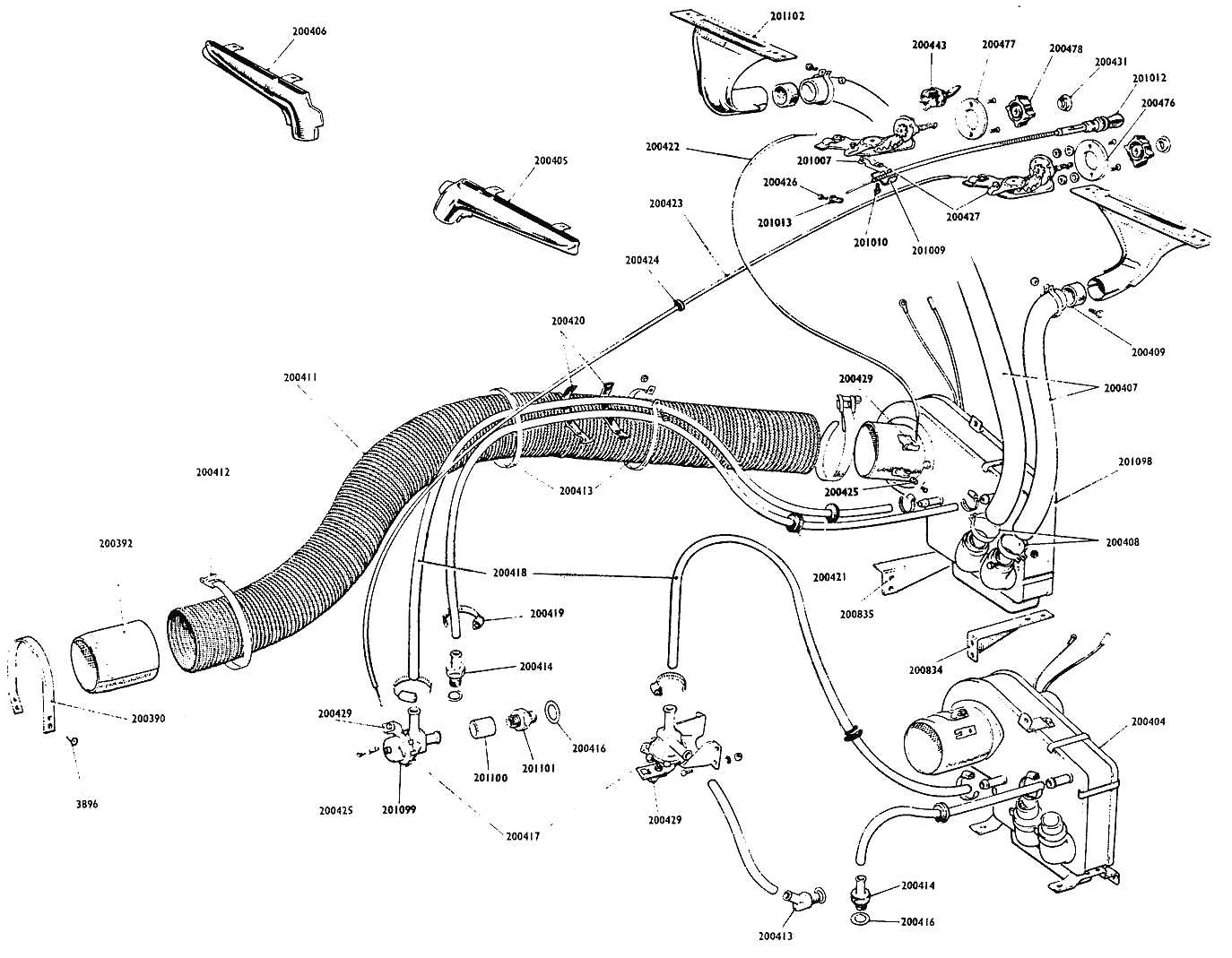
O1 THE SYSTEM The Heater Box is centrally mounted behind the engine
bulkhead, between the dashboard and front tunnel cover. The box is secured
by bolts to two side brackets. Mounted inside the box is a smal fin-and-tube
water radiator which is connected across the engine cooling system by two
flexible rubber hoses. The top flow hose circulates water from the front
cylinder head connection through a water valve to the heater radiator. The
second hose returns the water from the radiator to the cylinder head when
the engine thermostat valve is open.
In the Right Hand Drive car the water valve is fitted
directly into the side of the cylinder head using an adaptor union and
fibre washer. In the Left Hand Drive car the water valve is independently
mounted to the engine front bulkhead on brackets and secured by two
screws. This variation in position results in the water valve hose being
sliced in two. The longest length is used to link the valve to the elbow
adaptor which is fitted with a fibre washer to the side of the cylinder
head. The water valve is cable operated and trunnions secure
the cable to both valve and heater master control. Jubilee clips secure
the hoses, at the heater box and cylinder head connections. In addition
the hoses are clamped to the air inlet trunk by two straps. The fresh air
inlet is in the form of a large flexible trunk which supplies air to the
heater box. A metal support tube is held to the chassis with a
strap. and the flexible trunk is retained at both ends with two clamps. A flap mounted inside the heater box trunk connector
controls the flow of air to the car interior. A single trunnion and strap
secures the operating cable between the flap and master ventilator
control. Mounted in the base of the heater a second flap, again
cable operated, directs the air flow. With the flap open, the air, hot or
cold, is directed to the car interior. When the flap is closed, the air
passes through hoses from the rear of the heater to the
demisting/defrosting vents. The two hoses which connect the heater to the vents are
retained with clips and two adaptors are used to connect the hoses to the
demisting/defrosting vents. In the Right Hand Drive car the vents are mounted with
their nozzles pointing in opposite directions, but in the Left Hand Drive
the vents are 'handed' and both point outwards. The volume of air entering
the system can be boosted by throwing the 'Heater Fan' switch. The switch
operates the electric motor and fan mounted inside the heater box.
|
O2 REMOVAL OF HEATER UNIT 1.
Remove the two demisting/defrosting hoses from the rear
of the heater unit by releasing clips. 2.
Remove the two water hoses from the rear of the heater
by removing clips. 3.
Detach the air inlet trunk from the heater by removing
clip. 4.
Unscrew trunnion and strap located on the air inlet
trunk connecting tube and remove 'Push-Pull' cable. 5.
Remove heater fan and motor wires from 'Heater Fan'
switch. 6.
Unscrew bolts from heater box side mounting brackets
and lift out heater box. The replacement of
the heater unit is the reverse procedure as above O3 CONTROLS 1.
Admission of Air 2.
For Cold Air to Car Interior. With the'Push-Open Air' knob
IN : a.
Rotate master dash knob to 'Off'. b.
Set secondary dash knob for volume of air required, between
'Closed' and 'Open'. c.
To boost the volume of incoming air, throw the dashboard 'Heater
Fan' switch down. This will start the fan motor -switch off to receive air
under ram only. 3.
For heated Air to Car Interior. With the 'Push-Open Air'
knob IN : a.
Set the mister dash knob to desired position by turning from the
'Off' position through 'Warm' to 'Hot, setting is infinitely variable. b.
Set the volume of air required by infinite variation between
'Closed' and 'Open'. c.
To boost the volume of incoming air, throw the 'Heater Fan' switch
down. 4.
For Cold or Heated Air to Screen. Adjust as for 2 or 3
above, but with the dashboard 'Push-Open Air' knob pulled OUT. |
|
|
O4 ADJUSTMENTS
AND MAINTENANCE The
heater fan motor is wired to the dashboard ‘Heater Fan’ switch.
If a fault develops, the motor and fan can be withdrawn rearwards
from the heater box, by removal of its three flange bolts, for necessary
attention (See wiring diagram in Electrical System).
|
All
other heater controls are mechanically operated and are linked by flexible
wires to the two rotary knobs and the push-pull knob. The cables are screw
clamp retained and pre-set at the knob spindles and heater box levers. The
master dash knob operates a rotary water valve which is fitted in the top
flow water hose. Knob
spindles and inner cable ends can be lightly greased from time to time, to
ensure ease of operation. |
|