|
| |
Section N (
03/11/2010
)
ELECTRICAL EQUIPMENT
N.1 Lubrication and general
maintenance
N.2 Battery maintenance
N.3 Dynamo lubrication and maintenance
N.4 The control box
N.5 The fuse unit
N.6 The starter motor
N.7 Removing the starter from engine and dismantling
N.8 Ignition
N.9 The flashing lamp direction indicators
N10
Windscreen wiper
N11 Lighting
N12 Location and remedy of faults
NX01
Wiper motor
| |
|
|
|
Electrical System
The electrical system consists of the 12-volt generator, starter motor,
battery and ignition circuit. It also includes the circuits for the
instruments and other electrically controlled accessories.
GENERAL AND DATA
All electrical equipment is of 'Lucas' make, designed
for maximum service with minimum need for attention.
Battery:
12-volt. lead acid. 7-plate (tall). capacity 43 amp/hr. at 20 hr. rate.
Type BT7A.
or 12-volt. 9-plate (wet). capacity 57 amp/hr. at 20 hr. rate. Type BT9A.
or 12-volt, 9-plate (dry), capacity 57 amp/hr. at 20 hr. rate. Type BT9A.
Dynamo :
C39PV-2. Model 22265.
Cut-in speed 1.050 - 1.200 r.p.m. at 13 generator volts.
Max. output 19 amps at 1.980-2.150 r.p.m. at 13,5 generator volts.
Field resistance 6-1 ohms.
Distributor :
Type 1/2A4, contact breaker gap 0,012->0,015".
Ignition Control :
Type LA 12 (45053); current consumption, running 1 amp, stall 2-7 amp.
Control Box :
Type RB1O6-2.
Regulation Setting:
10°C (50°
F) 16,1 16,7 volts
20°C (68°F) 16,0
16,6 volts
30°C (86°F) 15,9
16,5 volts
40°C (104°F) 15,8 16,4
volts
Cut-in voltage 12,7-13,3
volts, drop of voltage 9-10 volts;
reserve current 3-5 amp.
Starter Motor:
Type M35G (25022). nominal voltage 12.
With armature locked. torque 7-7 lb/ft.
current 330-350 amp. voltage 7,5-7,1 volts. With armature running at 1,000
r.p.m. torque 4-5 lb/ft current 215-235 amp, voltage 9,1-8,7 volts.
Light running test. 45 amp at 8.500-1.000 r.p.m.
Fuse Unit:
Type 4FJ: fuses 35 amp.
Flasber Light Indicator :
Flasber Unit Type FL5. flasber lights front and rear. 12 volt. 21-watt,
Lucas 382.
Lighting :
Headlamp, 60/45-watt. Lucas 7002; sidelamp, Lucas 207; taillight. 12-volt.
6/21 -watt. Lucas 380-. number plate lamp. 12-volt. 6-watt. Lucas 989.
panel illumination, 12 volt, 2,2-watt. Lucas 987. warning lamps (ignition,
oil pressure and main beam). 12-volt. 2-watt-, flasher lamps. Lucas 987.
|
|
N1
LUBRICATION AND GENERAL MAINTENANCE
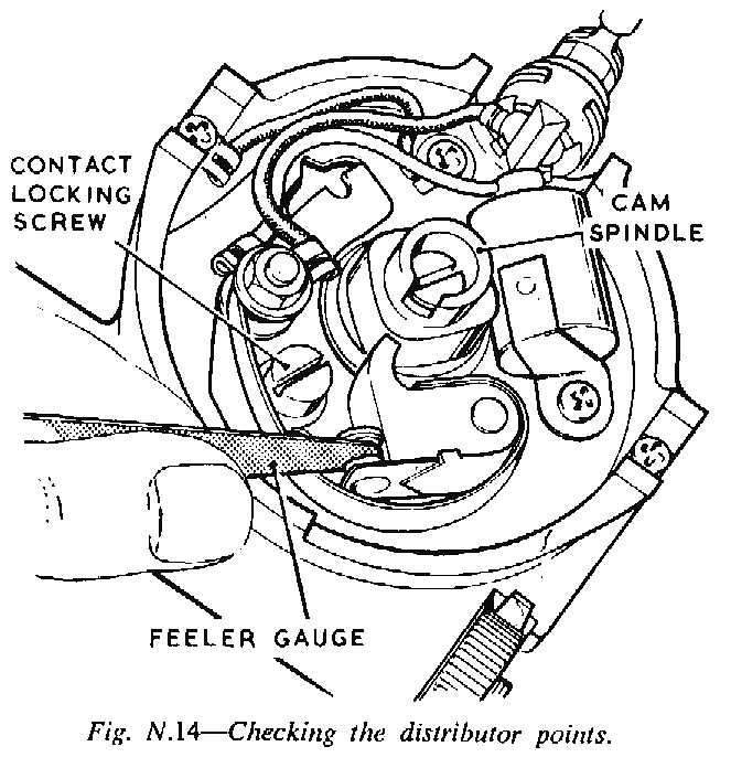
Check contact breaker after first 500 miles. The
contact breaker gap should be 0,015 inch when fully opened. Access to the
contact breaker is gained by opening back the two side clips and lifting
off the moulded cover. To check the setting, turn the engine slowly by
hand until a position of maximum opening is reached, then insert a feeler
gauge between the contacts. Owing to the initial bedding in of a new
contact set, the gap may need resetting. If so, slacken the two screws
which secure the fixed contact plate. Re-position the plate, which has two
slotted holes and rotates about the contact breaker lever pivot post,
until the gauge 0,015 inch can be inserted, as a sliding fit, between the
contact. Retighten the two screws. After adjustment recheck the gap to see
that no movement has taken place whilst tightening the screws.
Lubrication (every 6,000 miles)
Do not allow oil or grease on or near the contacts when
carrying out the following.
Remove the moulded cover and withdraw the pivot arm. To lubricate the cam
bearing, inject a few drops of thin machine oil into the rotor arm
spindle. Do not slacken or remove the screw located inside the spindle a
passage is provided beneath the screw bead to allow the lubricant to reach
the cam bearing. Lightly smear the outside faces of the cam with
Mobilgrease 2 or with engine oil.
For centrifugal timing control lubrication inject a few drops of thin
machine oil into the aperture in the contact breaker base plate through
which the cam protrudes.
For contact breaker pivot place a spot of Mobilgrease 2 or clean engine
oil on the top of the contact breaker lever pivot post. Refit the rotor
arm, carefully locating its moulded projection in the spindle keyway and
pushing it on as far as it will go. Refit the moulded cover.
Cleaning (every 6,000 miles)
Remove the moulded cover and clean the inside and
outside with a soft dry cloth. Pay particular attention to the space
between the terminals. Check the high tension pick-up brush to make sure
it moves freely in its holder. Remove the rotor arm and examine the
contact breaker. Rough, burned or blackened contacts can be cleaned with
fine carborundum stone or emery cloth. After cleaning, remove any grease
or metallic dust with a petrol-moistened rag.
Contact cleaning is made casier by removing the lever to which the moving
contact is attached. To do this, slacken the low tension terminal nuts and
lift the lever from its pivot and the end of the spring (wich is slotted)
|
|
|
|
|
|
from the terminal. After cleaning and trimning the
contacts, smear the pivot post with Rogosine Molybdenised non-slip oil or
with Mobilgrease 2. Reassemble the contact breaker and check gap setting
as previously described. Refit the rotor arm and moulded cover.
Performance Data
with contact breaker gap 0,015 inch. contact breaker
spring tension measured at contact 18 to 24 oz.. capacitor 0,18-0,23 mfd.
Advance due to automatic timing control, run distributor at 800 r.p.m.
Advance to be 11° max. Check advance at following decelerating speeds:
550 r.p.m. advance to be at 450 r.p.m. 5-1/2° -> 8-1/2°. at 300
r.p.m. 0°-> 3°. No advance below 200 r.p.m.
Contact breaker contacts must be renewed as a pair and
not individually. The gap must be set to 0,015 inch and rechecked after
500 miles.
N2
BATTERY MAINTENANCE
Wipe away any foreign matter or moisture from the top
of the battery, and make sure the connections and the fixing are clean and
tight. About every 1.000 miles or once a month, and more often in hot
wether, examine the level of the electrolyte in the cells. If necessary
add distilled water to bring the level up to the top of the separator
guard. The use of a Lucas battery filler will be found helpful in this
topping-up process, as it ensures that the correct electrolyte level is
obtained automatically and also prevents distilled water from being
spilled over the battery top. Distilled water should always be used for
topping up. In an emergency however, drinking water, clean rainwater or
melted snow may be used. Salt water, chlorinated water,
chemically-softened water and stagnant water must not be used.
Never use a naked light when examining a battery, as the mixture of oxygen
and hydrogen given off by the battery when on charge, and to a lesser
extent when standing idle, can be dangerously explosive.
Examine the terminals and, if they show an oxide film, scrape clean and
coat with petroleum jelly. Make sure the connections are clean and tight.
If the cable connections are removed from the battery lugs for any
purpose, or refitting, fill the screw with petroleum jelly, both before
and after fitting the self-tapping screw. If the connections are fitted
too tightly on the tapered battery posts, difficulty may be experienced
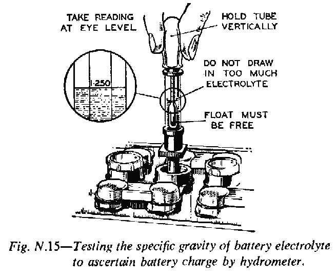
when they have to be removed. It is advisabie to check the state of charge
of the battery occasionally by measuring the specific gravity of the
electrolyte in each of the cells by means of a hydrometer. The specific
gravity of the electrolyte in a cell of serviceable condition will rise
during charging, and fall during a discharging period.
|
|
Measure the specific gravity of the acid in each cell
in turn with the hydrometer. To avoid misleading readings, do not take
hydrometer readings immediately after topping up. The readings given by
each cell should be approximately the same. If one cell differs
appreciably from the others, an internal fault in the cell is indicated. The
appearance of the electrolyte drawn into the hydrometer when taking a
reading gives an indication of the state of the plates. If the electrolyte
is very dirty, or contains small particles in suspension. It is possible
that the plates are in a bad condition. Specific gravity of electrolyte
(corrected to 60°F): fully charged. 1,270 - 1,290; about half discharged,
1,190 - 1,210, completely discharged, 1,110 - 1,130.
The specifick gravity of the electrolyte varies with the temperature so
for convenience in comparing specific gravities, it is always correct to
60°F, as follows: for every 5°F below 60°F deduct 0,002 from the
observed reading to obtain the true spceific gravity at 60°F. For every 5°F
, above 60°F add 0,002 to the observed reading to obtain the true
specific gravity at 60°F. The temperature must be that indicated by a
thermometer actually immersed in the electrolyte, and not the air
temperature. Compare the specific gravity of the electrolyte with the
values given in the table and so ascertain the state of charge of the
battery.
Never leave the battery in a discharged condition for any length of time.
Have it fully charged and every fortnight give it a short freshening
charge to prevent any tendency for the plates to become permanently
sulphated.
Discharge Test
A heavy discharge tester consists of a voltmeter. 2 or
3 volts full-scale, across which is connected a shunt resistance capable
of carrying a heavy current. Pointed prongs are provided for making
contact with the intercell connections. A good cell will maintain a
reading of 1,2 - 1,5 volts. depending on the state of charge, for at least
6 seconds. If however, the reading rapidly falls off, the cell is probably
defective. This test should not be carried out immediately after the vehicle
has completed a journey. Otherwise a misleading reading may be
obtained.
A battery that shows a general falling-off in efficiency, common to all
cells, wilt often respond to the process known as 'cycling'. This process
consists of fully charging the battery and then discharging it by
connecting it to a lampboard or other load, taking a current equal to tbe
charging current. The battery should be capable of providing this current
for at least 7 hours before it is fully discharged, as indicated by the
voltage of each cell falling to 1,8???. If the battery discharges in a
shorter time repair the cycle of charge and discharge.
Preparing New, Unfilled, Uncharged Batteries
Batteries should not be filled with acid until required
for initial charging. The specific gravity required for Britain
|
| |
|
|
|
and climates ordinarily below 90°F (32°C) is 1,270,
and for climates frequently over 90° (32°C) is 1.210 (both as at 60°F).
Electrolyte of the specific gravity required is prepared by mixing
distilled water and concentrated sulphuric acid, usually of 1,835 SG. the
mixing must be carried out either in a lead-lined tank or in a suitable
glass or earthenware vessel. Slowly add the acid to the water, stirring
with a glass rod. Never add the water to the acid, as the resulting
chemical reaction causes violent and dangerous spurting of the
concentrated acid. The approximate proportions of water are 2,8 volumes of
water to obtain specific gravity 1,270. and for 1,210 4,0 volume of
water.
Heat is produced by the mixture of acid and water and the electrolyte
should be allowed to cool before taking hydrometer readings or pouring the
electrolyte into the batterry. However, the temperature must not be below
32°F.
Carefully break the seals in the filling holes or remove the moulded pegs
from the vent plugs and half-fill each cell with electrolyte. Allow the
battery to stand for at least six hours (in order to dissipate the heat
generated by the chemical action of the acid on the plates before
continuing the filling to the top surface of the separator guard. Allow to
stand for a further two hours and
then proceed with the initial charge at the rate of 1,75 amps. until the
voltage and specific gravity readings show no increase over five
successive hours readings. This will take from
40 to 80 hourss. Some harmless frothing may occur during the first
few hours. This can be
minimised by reducing the charging current. Conversely, frothing will be
increased if the specified charging rate is exceeded.
This charge should not be broken by long rest
periods.
If however, the temperature of ay cell rises above the
100°F (37°70C) in this climate (hot climates 120°F) the charge must be
interrupted until the temperature has fallen at least 10°F below that
figure. At the end of the charge carefully check the specific gravity in
each cell to ensure that when corrected to 60°F. it lies within the
specified limits. If any cell requires adjustment, some of the over-strong
electrolyte must he syphoned and replaced by distilled water or, if too
high by acid of the strength used for filling in. Then continue the charge
for an hour or so and again check the specific gravity. Syphon-off any
electrolyte that may be above the top of the separator guard.
Preparing New Dry-charged Batteries For Service
Carefully break, the seals in the drilling holes and
fill each cell with correct specific gravity acid to the top of the
separator guard in one operation. The temperature of the filling room,
battery and acid should be maintained at between 60°F and 100°F.
|
|
N3
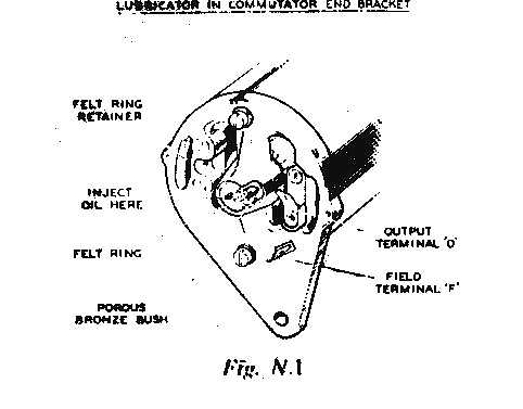
DYNAMO LUBRICATION AND MAINTENANCE
Every 12.000 miles or every year, whichever occurs
first, inject a few drops of high quality SAE 30 engine oil into the hole
marked 'oil' at the end of the C.E. bearing housing.
Brushgear
At every second lubricator period the generator should be removed from
the engine and the brushgear inspected by a competent autoobile
electrician.
Dynamo belt adjustment
Occasionally inspect the generator driving belt and, if necessary
adjust to take up any undue slackness by slackening the fixing nuts and
turning the generator on its mounting. Avoid overtightening the belt. The
tension needed being just enough to drive without slipping. See that the
machine is properly aligned, otherwise undue strain will be thrown on the
generator bearings
General
The dynamo is C40-1. part No. 22700. The generator is a shunt wound,
two-pole. two-brush, ventilated machine, arranged to work in conjunction
with a Lucas regulator unit. Holes in each end of the bracket allow a
pulley-mounted fan to draw cooling air trough the generator. This machine
is designed for use with a 5-inch
diameter fan ,and current voltage control under which circumstances its
maximum output of 22 amps. can be safely taken. When a 4-1/2 inch diameter
fan is used the maximum output must be limited to 20 amps.
The effective output is slightly reduced when compensated voltage is used
with either fan size.
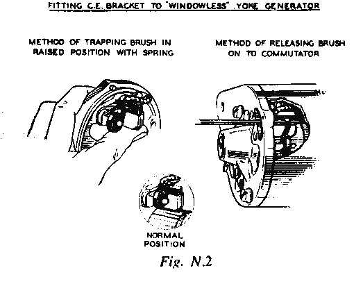
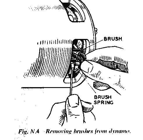
Brushgear (Checking with Yoke Removed)
Lift the brushes op into the brush boxes and secure them in that
position by positioning the brush spring at the side of the brushes. Fit
the commutator end bracket over the commutator and release the brushes.
|
| |
|
|
|
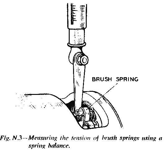
Hold
back each of the brush springs and move the brush by pulling gently on its
flexible connector. If the movement is sluggish, remove the brush from its
holder and ease the sides by lightly polishing on a smooth file. Always
refit brushes in their original position. Badly-worn brushes must be
replaced, and the new brushes must be fitted and bedded to the commutator.
The minimum permissible length of the brush is 9/32 inch. If the tension
is low on the brush springs, they must be replaced.
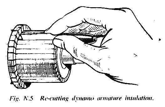
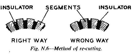
To
remedy a badly worn fabricated commutator, undercut the insulators between
the segments to a depth of 1/32 inch. Then take a light cut with a very
sharp (preferably diamond-tipped) tool. If a non-diamond-tipped tool is
used for machining the commutator should afterwards be lightly polished
with a very fine glass paper, never emery cloth. Whilst the C40 Generator
was designed to accommodate a commutator of moulded construction, initial
production also included machines having commutators of the older
fabricated type described in the previous paragraph.
|
|
Moulded commutators can be recognised by the exposed
end being quite smooth unlike that of fabricated commutators from which a
metal rollover and an insulating cone protrude. A moulded commutator can
be set skimmed during service. but care must be taken to see that the
finished diameter is not less than 1,50 inch. This operation should be
carried out by a skilled automobile electrician. If the moulded commutator
cannot be completely cleaned up without going below the specified diameter
it should be replaced.
Armature
Indication of an open-circuited armature winding will be given by burnt
commutator segments. If
armature testing facilities are not available, an armature can be checked
by substitution. To separate
the armature shaft from the drive end bracket, press the shaft out of the
drive end bracket bearing. When fitting a new armature, support the inner
journal of the ball bearing, using a mild steel tube of suitable diameter
whilst pressing the armature shaft firmly home.
|
| |
|
|
Removing and Dismantling the Dynamo
First disconnect the leads from the D and F terminals of the dynamo. Then
remove the fan belt. Unscrew the three bolts securing the dynamo to the
dynamo bracket attached to the cylinder head.
Take off the driving pulley. Remove the terminals from 'output' and
'field', unscrew the two through bolts using if available, a
wheel-operated screwdriver. As the bolts are being withdrawn, remove the
brush housing, the driving end bracket and armature assembly can then be
removed from the yoke.
To reassemble, reverse the dismantling operations. Before reassembly, see
that the ball bearing at the end is clean and well-packed with
high-melting-point grease.
Major overhauls of the dynamo should be carried out by a competent
automobile electrician.
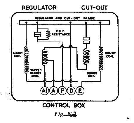
N4
THE CONTROL BOX
The control box controls the cut-out and voltage
regulator. The regulator controls the dynamo output in accordance with the
load on the battery and state of charge. Should the battery be discharged,
the output of the dynamo will be high, thus giving the battery a quick
charge and bringing it back to its normal state with the minimum of delay.
However, if the battery is fully charged, the dynamo is arranged to give a
small charge, which is sufficient to keep it in good condition without
causing damage to the battery by overcharging. The regulator controls the
dynamo, to give a boosting charge when the engine unit is first started
up, thus quickly restoring the battery energy used when starting.
The cut-out is an automatic switch for connecting and disconnecting the
battery with the generator. This is essential, otherwise the battery would
discharge through the generator when the engine is stopped or running at
low speed.
Regulator Checking and Electrical Setting
All settings are accurately adjusted before control
boxes leave the factory and must not be disturbed unnecessarily. If the
battery does not keep in a charged condition, or if the dynamo output
doesn't fall when the battery is fully charged, it may be advisable to
check the setting and if necessary to readjust. When the battery is in a
low state of charge, it is essential, before altering the regulator
settings to ascertain that
its condition is not due to a battery defect or a slipping dynamo
belt.
|
|
The checking and adjusting should be completed as
quickly as possible to avoid errors drue to the heating of the shunt
coil.
This operation can be carried out without removing the cover of the
control box. Connect a first-grade 0,20 moving-coil voltmeter between
control box terminals D and E. Remove control box cover in order to note
the instant of contact closure. Alternatively. switch on an electrical
load such as a pair of headlamps when the instant of contact closure wilt
be indicated by a slight flick in the voltmeter reading.
Start the engine unit and slowly increase its speed. Observe the voltmeter
pointer, if the flick occurs outside the limits 12,7 -> 13,3 volts, an
adjustment must be made. Stop the engine.
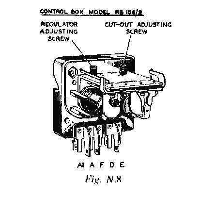
For voltage adjustment, remove the control box cover. Turn the control
relay adjustment screw (clockwise to raise the setting or anti-clockwise
to lower it) until the correct setting is obtained. Recheck the setting by
increasing the engine speed from zero. Restore the original connections
and refit the cover.
For drop-off adjustment, disconnect the cables from the control box
terminals A and A1 and join these cables together, connect a first-grade
0,20 moving-coil voltmeter between terminal A or Al and earth.
Start the engine and run up to speed. Slowly decelerate and observe
voltmeter pointer.
Opening of the contacts, indicated by the voltmeter pointer dropping to
zero should occur between the limits 8,5 -> 11,0 volts. If the drop-off
occurs outside these limits, an adjustment must be made. In this event
continue as follows. Stop the engine and remove the control box cover.
Adjust the height of the fixed contact by carefully bending to reduce the
drop-off voltage or away from it to raise the drop-off voltage. Recheck
the setting and, if necessary, readjust until the correct drop-off setting
is obtained. Restore the original connections and refit cover.
|
| |
|
|
|
Cleaning Contacts
To clean the voltage regulator contacts, use a fine
carborundum stone or silicon carbide paper. To clean the cut-Out relay
contacts, use a strip of fine glass paper, never carborundum stone or
emery cloth.
N5
THE FUSE UNIT
The fuse marked 2 (formerly A2) protects those
accessories which operate irrespective of the ignition being on or off,
the electric horn is in this category. The fuse marked 4 (or A4) protects
the accessories which are connected to operate only when the ignition is
switched on, namely, petrol gauge, flasher units, stop lamps and
windscreen wiper
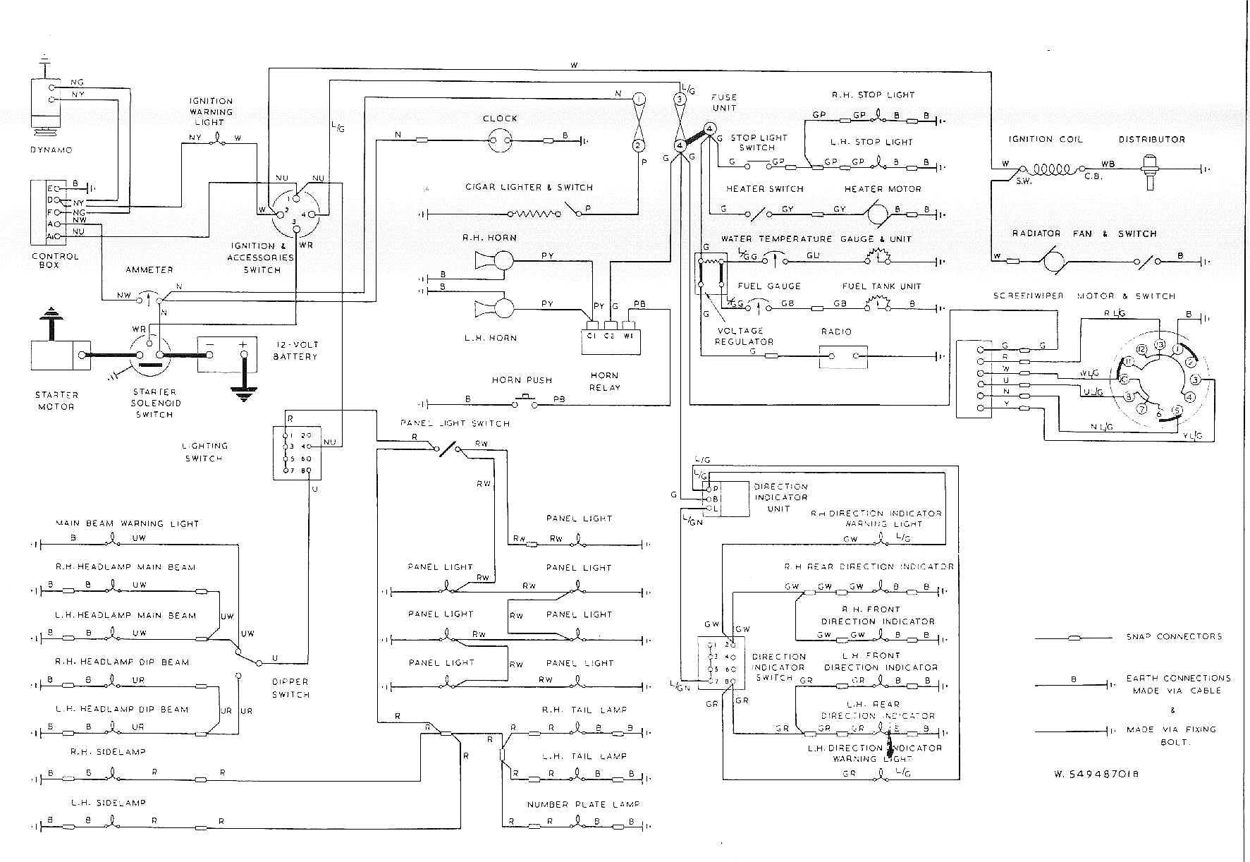
The above units protected by these fuses can easily be identified by
referring to the wiring diagram. A
blown fuse is indicated by the failure of all the units protected by it,
and confirmed by examination of the fuse, which can be easily withdrawn
from the spring clip in which it fits.
If it has blown, the broken ends of the wire will be visible inside
the glass tube. Before
replacing a blown fuse inspect the wiring of the units which have failed
for evidence of a short circuit or other faults which may have caused the
fuse to blow; remedy the cause of the trouble.
It is important to use only the correct replacement fuse, i.e. 35
amp; the fuse value is marked on a coloured paper slip inside the tube.
N6
THE STARTER MOTOR
The starting motor is a series-parallel wound
four pole four brush high-speed machine, fitted with a pinion which is
mounted on a quick start threaded sleeve.
The pinion engages with a ring gear fitted to the flywheel. The operating button is mounted on the instrument panel.
The following points should be observed when starting the engine
unit:
|
|
-
See that the controls are properly set.
-
Press the starter button and release immediately the
engine fires.
-
Do not operate the starter when the engine is running.
If the engine does not fire immediately, allow it to come to a stop
before pressing the starter button again.
-
Do not run the battery down by repeatedly pressing the
starter button when the engine will not start.
-
Do not use the starter motor to move the vehicle during
a temporary breakdown.
The starter will not require any attention during
normal operation.
Testing on the vehicle
In
the following test it is assumed the battery is in a fully-charged
condition. Switch on the lamps and press the starter button. If the lights
go dim, but the starting motor is not heard to operate, the current is
probably flowing through the starting motor winding but the armature is
not rotating. Check for an abnormally stiff engine or for the starter
pinion being meshed permanently with the ring gear on the flywheel, that
could be caused
by the starter being operated while the engine was
still moving, if so, the starter motor may have to be removed from the
engine for examination (see below also). Should the lamps retain their
full brilliance when the starter button is operated check the circuit for
continuity from battery to starting motor via the starter switch, and
examine the connections at these units. If the supply voltage is found to
be applied to the starting motor when the
|
| |
|
|
|
switch is operated, an internal fault in the motor is
indicated and the unit must be removed from the engine unit for
examination.
Sluggish or slow action of the starting motor may be due to a discharged
battery or to a loose connection forming a high resistance in the motor
circuit. If the motor is heard to operate, but does not crank the engine,
indication is given of damage to the drive.
Difficulty experienced with the starter not meshing corectly with the
flywheel could be due to dirt or engine oil on the starter drive,
preventing the free movement of the pinion and barrel assembly on its
sleeve, the sleeve pinion should be washed with paraffin. Alternatively
the drive may have been damaged owing to misuse.
Should the starter pinion become jammed in mesh with the flywheel, it can
usually be freed by turning the starter armature by means of a spanner
applied to the shaft extension at the commutator end.
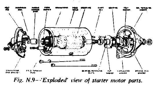
N7
REMOVING THE STARTER FROM THE ENGINE AND
DISMANTLING
Every 12.000 miles the commutator and brushgear should
be examined. It is advisable to remove the starter from the engine for
this purpose. Disconnect one of the battery cables at the battery to avoid
any danger of causing short circuits.
Disconnect the cable from the starter motor, remove the two bolts securing
the starter motor to the engine plate and clutch housing, the starter
motor can then he removed. Should any of the parts of the drive be worn or
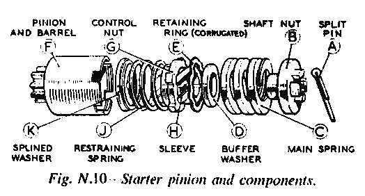
damaged they must be replaced, the drive is dismantled by first removing
the split pin from the nut at the end of the starter drive. Hold the
squared starter shaft extension at the commutator end by means of a
spanner and unscrew the shaft nut. Lift off the main spring, buffer
wasber, remove the corrugated retaining ring from the inside of the pinion
barrel assembly, control nut, sleeve and restraining spring will now slide
off. Withdraw the splined washer from the armature shaft and remove the
pinion and barrel.
|
|
The assembly of the drive is a reversal of the
dismantling procedure.
Should either the control nut or screwed sleeve be
damaged, then a replacement assembly of screwed sleeve and control nut
must be fitted. These components must not be renewed individually.
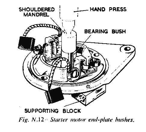
Remove the cover band, hold back the brush springs and
lift the brushes from their holders. Remove the nuts from the terminal
post which protrudes from the commutator end bracket. Unscrew the two
through bolts from the commutator end bracket and remove the commutator
end bracket from the yoke. Remove the driving end bracket and drive from
the starting motor yoke. If it is necessary to remove the armature from
the driving end bracket it can be done by means of a hand press, after the
drive bas been dismantled. Reassemble by reversing the above procedure.
Commutator
The commutator should be clean, free from oil or dirt and should have
a polished appearance. If it is dirty, clean by pressing a fine dry cloth
against it, while the starter is turned by hand by means of a spanner
applied to the squared extension shaft. Access to the squared shaft is
gained by removing the thimble-shaped metal cover. Should the commutator
be very dirty moisten the cloth with petrol.
The insulators between the commutator segments MUST NOT BE UNDERCUT
Brushgear
Remove the metal band cover and examine the brushes, check that these
move freely in their holders by holding back the brushes spring and
pulling gently on the flexible connections.
|
| |
|
|
|
If a brush is inclined to stick, remove it from its
holder and clean the sides with a petrol-moistened cloth. Be careful to
replace brushes in their original position in order to retain the bedding.
Replace the brushes.
Two of the brushes are connected to terminal eyelets attached to the brush
boxes on the commutator end bracket, and two are connected to the
aluminium field coils. If the brushes are worn so that they do not bear on
the commutator or if the flexible connections are exposed on the running
face, they must be replaced. To do this proceed as follows. Cut off the
original brush flexible 1 inch (3 mm approx.) from the aluminium. Clean up
and tin the original resistance brazed joint. Open out the loop of the
replacement brush flexible. Tin the loop, taking care not to allow any
solder to run towards the brush. Place the original joint within the loop.
Squeeze up and solder. The brushes are pre-formed so that the bedding to
the commutator is unnecessary.
N8
IGNITION
Distributor
A centrifugally-operated timing control mechanism is mounted on the
driving shaft immediately beneath the contact breaker. The mechanism
consists of a pair of spring loaded governor weights linked by lever
action to the contact breaker cam. At low engine speed the spring force
maintains the cam in position in which the spark is slightly retarded. At
high engine speed the governor weights swing outwards to turn the contact
breaker cam thereby advancing the spark.
The capacitor is of metallised paper construction, and bas the property of
being self-healing. Thus in the event of a dielectric breakdown occuring,
the metallic film around the point of rupture is vaporised away by the
heat of the spark. In this way permanent short circuits are prevented.
The centre portion of the resistive pick-up brush is made of a hard
resistive carbon compound whilst the end portions are of a soft carbon.
Since the brush is in circuit between the ignition coil and distributor
high tension terminals this produces a measure of radio and television
interference. On no account must a short non-resistive brush be used to
replace a long resistive brush.
Ignition Timing
Remove the sparking plugs and rotate the engine until the raised
timing boss on the cylinder front cover and the notch on the crankshaft
pulley rim coincide. At this position, the No. 1 piston will be at Top
Dead Centre on the compression stroke. With the distributor cap removed,
ensure that the rotor arm is facing the offset slot in the drive shaft in
the cylinder block. Before refitting the distributor to the engine, hold
the distributor body so that the knurled micro adjuster is parallel to the
engine and position the rotor
arm in |
|
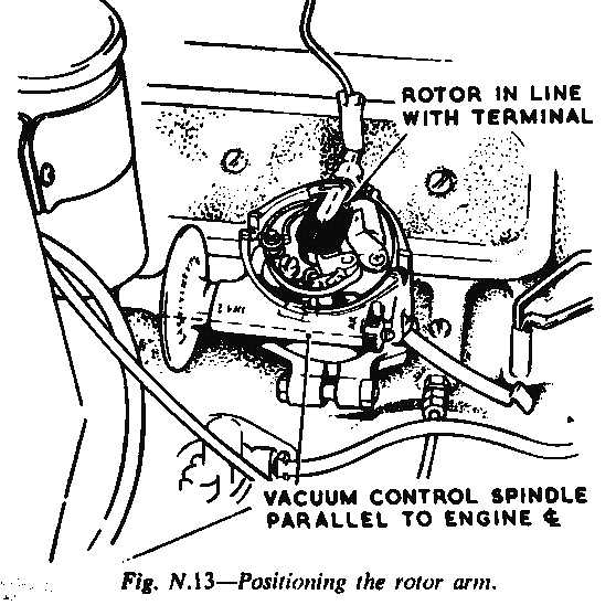
line with the low tension terminal. Refit the distributor
and secure the body clamp plate to the cylinder block by means of the two
clamping screws. Check that the micro adjusting nut is set to the fourth
line on the graduated scale which is the zero setting. Having refitted the
distributor, the body clamp bolt should be slackened and the distributor
head turned clockwise until the contact points are just breaking. The
exact position can be determined by inserting a very thin piece of paper
between the points when they are fully closed, and gently pulling on the
paper whilst the distributor head is being turned. When the paper can be
eased out this will indicate that the points are about to break.
Tighten the clamp bolt and re-check the adjustment.
Coil
The ignition coil requires no attention other than seeing the terminal
connections are tight, and that the extension is kept clean, particularly
between the terminals.
H.T. Cables
The high tension cables must be carefully examined, and
any which have the insulation cracked, perished or damaged in any way must
be replaced with rubber-covered ignition cable. The method of connecting
the cables to the coil and distributor cap is to thread the knurled
moulded nut over the cable, bare the end of the cable for approximately 1
inch, thread the wire through the copper washer removed from the original
cable, bend back the wire strands, screw nut into its terminal.
|
| |
|
|
|
Ignition Waming Lamp Switch
The ignition switch, besides forming a means of starting and stopping
the engine unit, is provided for the purpose of preventing the battery
being discharged by the current flowing through the coil windings when the
engine is stopped. A red warning lamp is provided in the instrument panel
which lights immediately the engine is switched on, also whilst the engine
is ticking over or is stationary, reminding the driver to switch off.
Should the warning lamp bulb become defective, this will in no way affect
the ignition system, but should be renewed as soon as possible, in order
to safeguard the battery.
N9
THE FLASHING LAMP DIRECTION INDICATORS
The flasher unit model F15 is housed in a small
cylindrical container, in which the alternate heating and cooling of an
actuating wire causes the operation of a main armature and associated pair
of contacts in the flasher lamp supply circuit. At the same time, a
secondary armature operates pilot contacts which cause a warning light to
flash when the system is functioning correctly. Failure of warning light
to flash will indicate a fault in the system.
Flasher units cannot be dismantled for rectification; a defective unit
must be replaced, care being taken to reconnect as the original.
Switch
There is a two-way-and-off switch for controlling the flasher lamps.
The connection should be checked occasionally and tightened if loose. Bulb
is Lucas No. 987, 12- volt, 2-2-watt, M.E.S. cap.
N10
WINDSCREEN WIPER
The motor and gearbox unit is mounted in the engine
compartiment on three parts cast integrally with the unit body. The rotary
motion of the motor armature is converted to the reciprocating motion of
the cable rack by means of a single-stage worm and nylon gear reduction
drive. A connecting rod and crosshead in the gearbox actuate the cable
rack which passes through protective outer tubing to the wheel boxes. The
rack consists of a flexible core of steel wire wound with a wire helix
which engages with a gear in each wheel box and thus transmits the
reciprocating motion to the wiper arm spindles. To start the windscreen
wiper, turn the rotary switch on the left hand side of the instrument
panel. The arms and blades return automatically to the parking position
whatever their whereabouts when switched off. As the gearbox, cable rack
and wheelboxes are greased during manufacture, they do not require any
periodic lubrication.
|
|
Replacement of Arm Blade Assembly
The screw securing the arm and blade assembly is designed so that it
also takes the form of an extractor. To remove the arm and blade assembly,
slacken the flxing screw from the wiper spindle.
N11
LIGHTING
General
The headlights are sealed beam units. The filaments are sealed in the
glass unit which consists of the lens and the reflector. In the event of a
bulb blowing, only the complete unit is replaceable.
Lamp Rim Removal
To remove the lamp rim, unscrew the securing screw at the base of the
rim. The rim can then be lifted off, leaving the glass bulb and reflector,
which are permanently sealed together as a unit, still in position. The
replacement of the lamp rim is the reverse procedure.
Scaled Beam Unit Removal
To remove the unit slacken the three screws securing the inner bezel.
The unit can then be lifted out and the connecting plug at the rear of the
unit disconnected. When removing, turn the unit so that it can be drawn
away leaving the securing screws in position. The elongated slots on the
bezel have one end slightly enlarged to facilitate this.
Replacement of Sealed Beam Unit
The reassembly of the unit is a reversal of the above instructions.
Headlamp Alignment
The headlamps should be set so that the main driving beams are
straight ahead and parallel with the road surface and with each other. If
adjustment is necessary, remove the lamp rim as previously described.
Adjust both lamps to the correct position in the vertical plane by means
of the vertical adjustment screw at the top of the seal beam unit. To
raise the beam, the screw must be turned in a clockwise direction and to
lower the beam, in an anti-clockwise direction. The two screws positioned
on either side of the unit are for the horizontal adjustment of the beam.
Alignment should be carried out with the empty car standing on a level
surface at a distance of 25 feet from a white wall or screen. The wall
should be in semi-darkness and shielded from direct light so that the
bright spots from the beamlamps can be clearly defined.
Number Plate Lamp
Remove the two front-cover screws to gain access to the bulb. The bulb
is Lucas No. 989, 12-volt, 6-watt, M.E.S. cap.
|
| You
might want to have a look at a thorough description of wiper motor etc. |
|
|
| |
|
|
|
Oil Waming Lamp
The oil warning lamp should light only when the engine is at rest with
the ignition switched on, and immediately the engine reaches speed should
become extinguished, thus indicating that the oil is being circulated
under pressure in the engine lubricating system. To replace the bulb
withdraw the bulb holder from its housing at the rear of the panel. The
bulb is Lucas No. 987, 12-,volt, 2-watt, B.A.7.S cap.
!
Never seen this on my car!
Ignition Waming Light
The ignition warning light serves the dual purpose of reminding the
driver to switch off the ignition before leaving the vehicle and of acting
as a no-charge indicator. It should only operate with the engine at rest
or turning over slowly, and should become extinguished immediately the
engine revolutions are increased; failure to do so indicates a fault in
the charging circuit. The bulb is Lucas No. 987, 12-volt. 2-watt, B.A.7.S.
cap.
Flasher Lamp
Access to the rear flasher lamp bulb is by removing the two screws
securing the lens. For access to the front flasher lamp, peel back the
rubber surround to release the rim and lens. The bulb is Lucas No. 382,
12-volt, 21-watt, S.B.C. cap.
Side Lamp
To gain access to the bulb, peel back the rubber surround to release
the rirn and lens. the bulb is Lucas No. 207, 12-volt, 6-watt, S.B.C. cap.
Stop and Tail Lamps Access to the bulb is gained by rernoving the two
screws securing the lens. the bulb is Lucas No. 380, 12-volt, 6121 -watt,
S.B.C. cap.
Cleaning Lamps
Chromium-plated surfaces should be washed with plenty of water and
when the dirt is removed they should be polished with a chamois leather or
soft dry cloth. Do not use metal polishes on chromium plating.
Electric Horn
The vehicle has two horns, one high and one low, positioned left and
right in front of the radiator. All horns before being passed out of the
works are adjusted to give their best performance and will give a long
period of service without attention. Should either horn fail or become
uncertain in performance, ascertain that the trouble is not due to faulty
wiring, or discharged battery, a short circuit in the born will cause the
fuse to blow. If the fuse is blown examine the wiring for fault, rectify,
then replace fuses.
To adjust either hom remove the cover plate which is secured by one fixing
screw at the rear of each horn; the points can then be adjusted. If, after
this operation bas been carried out, the horn is still at fault it should
be returned to a Lucas Agent for rectification.
|
|
N12
LOCATION AND REMEDY OF FAULTS
Every precaution is taken to minimise all possible
causes of trouble; failure may develop through lack of attention to
equipment or damage to wiring. The sources of many troubles are by no
means obvious, often a considerable amount of deduction from the symptoms
is needed before the cause of the trouble can be traced. The engine may
not respond when the starter switch is depressed, but the starter motor is
dependent on the battery, so that a faulty connection or a flat battery
could be one cause of this faiture. If the battery should be flat this
would be due to the dynamo failing to charge the battery, due to a slack
fan belt or a faulty connection in the charging circuit. If after carrying
out the examination, it is not possible to trace the cause of the trouble,
it is advisable to contact the nearest Lucas Service Depot or Agent.
Failure of Engine to Fire
Make sure the terminals on the battery have a good connection, also
that the battery is fully charged. The simplest method of testing the
battery is to ensure that the lamps give a good light, and that the
starter will turn the engine. Should the battery be flat, this must be
recharged from an independent electrical supply.
Make sure the contacts are correctly set for starting.
Remove the cable from the centre terminal of the distributor cap and hold
this so that the end is about a 1 inch away from any metal part of the
chassis whilst the engine is turned over slowly. If the spark jumps the
gap regularly, the coil and distributor are functioning correctly.
|
| |
|
|
|
The sparking plugs should be examined. If these are
clean and the gaps correct, the trouble could be due to carburettor or
petrol supply.
If the coil does not spark in the test, check for a fault in the low
tension wiring.
Remove the distributor cap. If no spark occurs between the distributor
contacts when quickly separated by the fingers, with the ignition switched
on, examine all cables in the ignition circuit for a faulty wire, making
sure that all connections are tight.
If no fault is found with the wiring and connections, examine the contact
breaker points, they may require cleaning and gap resetting to 0,015 inch.
Engine Misfires
Ensure that the distributor contacts are thoroughly clean, and the gap
correctly set at 0,015 inch. Run the engine at an idling speed slightly
above normal, short-circuit each sparking plug in turn, using an insulated
screwdriver placed across the plug terminal and contacting the cylinder head.
When a faulty plug is short-circuited, this will not cause a noticeable
change in the running note, whereas the shorting of a sound sparking plug
will increase the roughness of the engine unit. Having located any faulty
cilinders stop the engine, remove the cabine from the sparking plug
terminal, restart the engine, hold the cable about 1 inch from the plug
terminal or cylinder head, if the sparking is strong and regular, the
fault lies with the sparking plug which should be removed, cleaned, and
the gap reset to 0,018 inch, or be replaced with a new plug.
Should there be no spark, or only a weak and intermittent spark, examine
the cable from the plug to distributor.
Renew the cable if the rubber is cracked or perisbed.
Clean the distributor moulded cover and check the free movement of the
carbon brush. Should the brush need replacing, make sure the correct type
is obtained. On no account must the standard
|
|
non-resistive brush be fitted, as this is too short for
use with the model 1/2A4 distributor and would not make contact with the
rotating electrode. If tracking has occurred, this will be indicated by a
thin black line, usually between two or more electrodes; a replacement
distributor cover must be fitted. If tests show all four plugs to be
sparking regularly, the trouble could be due to valve seating or burnt
valves, carburettor, or petrol supply.
Battery in Low State of Charge
This will be indicated by lack of power when starting, poor lighting,
and hydrometer readings below 1,190 – 1,120. It could be due to the
dynamo not charging, giving a low intermittent output, or the control box
requiring resetting. The ignition warning light will not go out if the
dynamo is not charging, or will flicker on and off in the event of an
intermittent output.
Examine the charging and field circuit wiring, tighten any loose
connections, replace any broken cables. Pay particular attention to the
battery connections. Make sure the dynamo driving belt is correctly
adjusted; slackness can be taken up by slacking off the dynamo fixing
bolts to enable the dynamo to be turned in its mounting bracket, retighten
bolts after carrying out the necessary adjustment.
If the cause of the trouble is not apparent the equipment should be
examined by a Lucas Service Depot or Agent.
Overcharged Battery
This will be indicated by burnt out bulbs, frequent need for the
topping up of the battery and high hydrometer readings.
Check the charging current when the car is running steadily with a fully
charged battery, with all lights and accessories in use the charge reading
should be 1 amp. If in excess of this value the regulator setting should
be tested and adjusted. If necessary, by a Service Depot or Agent.
Starter Motor
If the starter motor lacks power or fails to turn the engine, first
check to ensure the trouble is not due to a flat battery. Examine the
connections to the battery, starter, and starter button, seeing that these
are tight and the cables connecting these units are not damaged. A further
possibility is that the starter pinion may have jammed in mesh with the
flywheel, although this is not a common occurrence. To disengage the
pinion, rotate the squared end of the starter shaft by means of a spanner.
Should the starter operate and not crank the engine, this fault could be
caused if the pinion and barrel assembly of the starter drive is not
allowed to move along the screwed sleeve into engagement with the
flywheel, possibly because engine oil or dirt has collected on the screwed
sleeve. Thoroughly clean the sleeve, either with petrol or paraffin.
|
| |
|
|
 |
|
|
|
| |
|
|
|
Lighting Circuit
If the lamps give insufficient illumination, test the battery to
ensure it is properly charged, if recharging is necessary this should be
carried out by either a long period of daytime running or from an
independent electric supply. Check the setting of the lamps. Should the
bulbs be discoloured from long service these should be replaced. |
|
If the lamps light when switched on, then gradually
fade, check as paragraph one. Should the brilliance of the lights vary
with the speed of the car, check as paragraph one. Also examine the
battery connections, seeing that they are tight; replace any faulty
cables.
|
| |
|
|
Common Technics
|