Section M ( 07/01/2014 )
BRAKES
M.1 Data
M.2 Installation of brakes
M.3 General instructions
M.4 Handbrake
M.5 Central valve tyre master cylinder
M.6 Description, operation and removal of the brakes
M.7 General maintenance
|
|
||
|
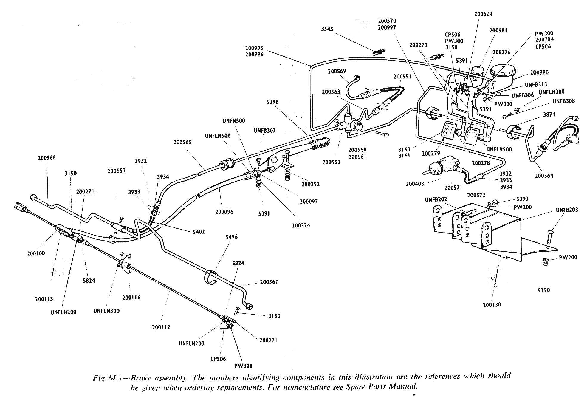
M1 DATA Tbc Girling hydraulically operated braking system
employs disc type brakes on the front wheels and brake shoes on the rear
wheels. The rear brake shoes are of the slidiing type and incorporate the
lever handbrake mechanism. Make - Girling Type: Front: Disc Rear : Sliding Shoe Pedal Free Movement – 1/4 in. approx. Handbrake . Pull-up type Handbrake Operation – Mechanically on rear Total Braking Area - 301 sq. in. Diameter of Discs. 11 inches Inside Diameter of Drum : Front 10-1/2 in. Rear 9 in Shoe lining - Width 1-3/4 in. M2 INSTALLATION OF BRAKES The brakes on all four wheels are hydraulically
operated by foot pedal application, directly coupled to a cental valve
type of master cylinder. The master cylinder includes a reservoir in which
the brake fluid operating pressure is originated. The associated system
coconsists of metal piping, flexibie hose and unions. On depressing the
brake pedal, liquid is pressed trough the system to the front ind rear
brakes via a five-way union. At each front wheel fluid is delivered to the
caliper unit where a two-way union drives the fluid to the rear of the
brake pads forcing them outwards against the disc. From the five-way union
to a single pipe carries oil to the two-way union, mounted on the rear
axle, which passes the fluid to a brake cylinder on each wheel. The
cylinder piston is forced outwards to operate the front and trailing brake
shoes. When the foot pedal is released, springs return the front wheel
caliper pads and the rear wheel brike shoes to their normal position. A
mechanical linkage actuated by the hand lever operates levers located on
the rear wheel back plates to operate the brake shoes independently of the
hydraulic braking system. M3 GENERAL INSTRUCTIONS Absolute cleanliness must be observed when dismantling
any part of the braking system. All road dirt must he removed and the
brake components disantled on a bench covered with clean paper sheets; any
internal hydraulic
|
parts or rubber seals should not be handled with greasy
hands or rags. Do not wash units in petrol, paraffin or trichlorethylene,
these fluids cause damage to rubber parts. All internal metal parts should
be washed in a tray of clean brake fluid. dried with clean dry lint-free
cloth and laid out in assembly order on clean paper. Examine all rubber
parts carefully for signs of 'sponginess' or perishing and renew if
necessary, soaking the new parts in brake fluid before assembly. Main
castings may be cleaned in nornal cleaning fluid and dried with clean dry
lint-free cloth and a jet of clean dry air. After cleaning and inspection
parts are to be dipped in clean brake fluid and assembled wet to aid
lubrication. Stop light Switch The hydraulically operated stop switch is fitted to the
five-way union. The union distributes hydraulic oil from the master
cylinder to the four wheels and is bolted to the forward left hand side of
the chassis. M4 HANDBRAKE The handbrake system, to the rear wheels only, operates
from a pull-on lever situated hetween the driver's seat and the propeller
shaft tunnel. The brake lever is secured by two bolts and nuts to a
special bracket welded to the chassis. The cabine assembly, consisting of
an outer case and inner cable. leads from the lever to a yoke near the
rear axle. From the yoke the cable leads to the rear ofside wheel, (right
hand drive) or to the rear near side wheel (.1eft liane] drive). On both
drives a transverse cable leads from the yoke to each rear wheel. A grease
nipple is located on the underside of the outer case. Removal and Assembly of handbrake Cables To remove the trztiisverse cabine. disconneet cable
elevis pin by reiiioving elevis pin frons brake cable yoke. remove elevis
fro!ii wheel brake Fit ncw cable "tssenibly. cable sluck can be taken
tip on the adjustiii£ nut at tbreaded end of c"thie. Eiistire tliat
loek nut is fiilly tiglitened. To reiliove iiiain ctble assenibly.
discotitiect elevis at wheel brake ariii Plaid at liatidbrake connectioii.
Fit ncw cahie ass.-nibly and tidjust at cievis a(Ijtisting nut'. eristit'e
thztt the loek nul is fuity tiglitene@l after adjtistiiieilt. To remove
handbrake lever, disconneet the cable elevis to the lever, remove the two
lever securing holts and lift of the handbrake. To fit the handbrake,
reverse the above directions. After adjustment of the rear brakes. the
handbrake lever sometimes has eccessive free movement. To correct this the
following procedure is adopted. Jack up both rear wheels and lock the
brakes by means of the adjusters (handbrake off).
Adjust cable length and release the adjusters until the wheels turn
freely.
|
|
|
M5 CENTRAL VALVE TYPE MASTER CYLINDER The master cylinder of the hydraulic brake system
consists of an alloy body housing, the inner assembly and a reservoir. The
inner assembly is made up of the push rod. dished washer, spring retaining
clip, plunger, plunger seal, spring thimble, plunger return spring, valve
spacer, spring washer, valve stem and valve seal. The open end of the cylinder is protected by a rubber
dust cover. To remove the master cylinder from the chassis, disconnect the
pressure pipe union, split pin, clevis pin and the two bolts securing the
master cylinder to the chassis; unscrew the clevis from the push rod. Dismantling the Master Cylinder Remove the filler cap and drain off the fluid. Pull
back the rubber dust cover and remove the circlip, using a pair of
long-nosed pliers.-,. Remove the push rod and dished washer to expose the
plunger with seal attached. Remove this assembly complete and separate by
lifting the thimble leaf over the shouldered end of the plunger; case the
seal off the plunger. Depress the plunger return spring, allowing the
valve stem to slide through the elongated hole in the thimble to release
the tension spring, remove thimble, spring and valve complete. Detach
valve spencer, exercising care with spacer spring washer located under the
valve head; remove seal from valve head. All parts should be carefully examined for wear. damage
or distortion and new parts fitted if necessary. Reassembly of the Master Cylinder Replace the valve seal with flat side correctly seated
against the valve head. Locate the spring washer to the underside of the
valve head and hold in position with valve spacer; the spacer legs must
face towards the valve seal. Refit the plunger with the return spring
positioned centrally on the spacer, insert the thimble in the return
spring and depress until the valve stem engages through the thimble
elongated hole, checking that the spring is still centrally located on the
spacer. Fit a new plunger seal to the plunger. With the flat of the seal seating against the plunger face insert the reduced end of the plunger into the thimble until the thimble leaf engages under the plunger shoulder, press firmly to locate thimble leaf. Smear the assembly with Girling Brake Fluid and
position the assembly, valve end first into the cylinder bore, easing the
plunger seal lips into the bore. Refit the push rod into the cylinder;
ensure that the dished side of the washer is seating under the spherical
head. Insert circlip into cylinder bore groove and replace dust cover.
Refit the cylinder to the chassis and reconnect to footbrake pedal. |
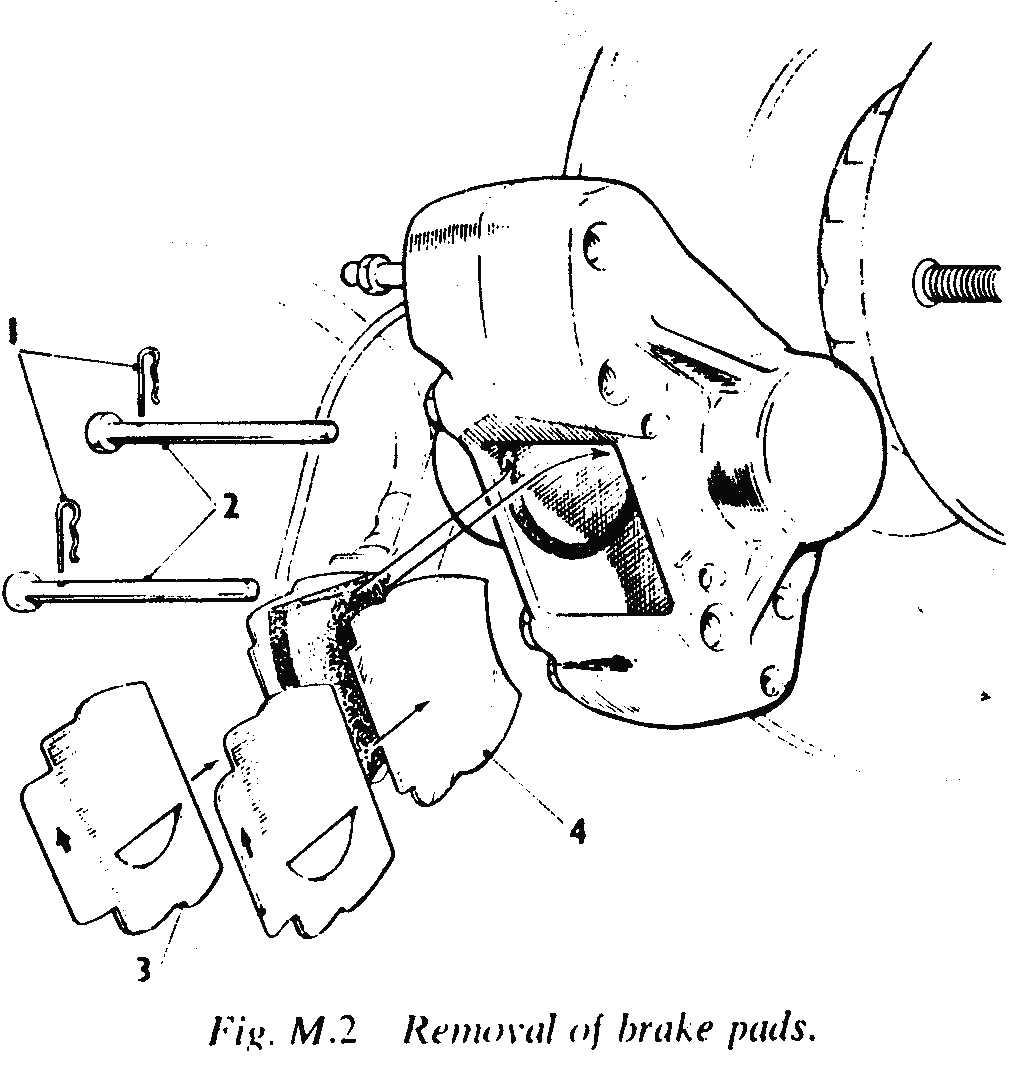
M6 DESCRIPTION OPERATION AND REMOVAL OF THE BRAKES Front Brakes Braking is achieved by the action of hydraulically
operated pads. housed in a caliper unit, on a disc mounted on the stub
axle. The Girling caliper plate is secured to the stub axle
by four bolts and holds the caliper unit and the hydraulic pipe bracket.
The caliper unit and the bracket are each secured by two bolts to the
plate. The brake disc is secured to the hub by four bolts. Before removing the caliper unit the wheel must be
jacked up and the hydraulic system bled at the bleed valve to release
fluid pressure: the pipe line can now be disconnected from the caliper
unit. There is no adjustment on the front brakes, the pads
are in constant light contact with the discs and must be renewed when
there is insufficient contact or pad thickness. To renew the brake pads,
remove the spring pins from the tubular pins retaining the pads and
withdraw the tubular pins. Lift out the worn pads and fit new ones, lock
in position with tubular pins and spring pins.
|
|
|
Bleeding the Hydraulic System Bleeding is necessary any time a section of the
hydrautic system has been disconnected. or if the level of the brake fluid
has been allowed to fail so low that
air has entered the master cylinder. With al the hydraulie connections
secure and the supply tank reservoir 'topped-up' with fluid, slaeken off
all the brake shoe adjusters where fitted. as far as they will go. Remove
the rubber cap from the bleed nipple farthest away from the master
cylinder and fit a bleed tube over the bleed nipple. immersing the free
end of the tube in brake fluid container in a clean jar. UNSCREW the bleed nipple approximately threequarters of
a turn. Operate the brake pedal with slow flat strokes until the fluid
entering the jar is free of air bubbies. lt is advisable to allow two or
three seconds pause before every downward stroke. During a down stroke of
the brake pedal tighten the bleed nipple, remove the bleed tube and
replace the bleed nipple dust cap. Under no circumstance must excessive
force be used when tightening the bleed screw. This process must now be repeated for each bleed nipple
at each brake. Always keep a
careful check on the supply tank during bleeding since it is most
important that a ffull level is maintained.
Should air reach the master cylinder from the integral supply tank
the complete operation of bleeding will have to he repeated. After
bleeding, top up the supply tank to its correct level and adjust brakes,
as described. Never use the fluid which has been bled from the system to
top up the supply tank, because it may have, to some extent become
aerated. Fluid which appears dirty or emulsified should he bled from the
system and replenished with fresh Girling Crimson Brake Fluid. Essential Precautions 1 . Use only the genuine Wakefield Girling Brake Fluid
(Crimson) obtainable in sealed quart tins. 2. Always ensure extreme cleanliness when dealing with
any parts of the hydraulic system. Never handle rubber seals or internal
hydraulic parts with greasy hands. 3. Always use clean brake fluid or alcohol when
cleaning internal parts of the hydraulic system. On no account should
petrol or paraffin be allowed to contact these parts. 4. Examine all seals carefully when overhauling
hydraulic cylinders and replace. with genuine Girling spares, any of which
shows sings of wear or damage. Take
care not to scratch the highly finished surface of the pistons. 5. Always pack the protective rubber boots in all
Girling Master Cylinders, and external wheel cilinders. with Rubber Grease
No. 3. obtainable in convenient 2 oz. collapsible tubes from any Girling
Agent. (Never use ordinary white brake grease for this purpose.). 6. When a system has heen contaminated with mineral
oil, master and wheel cylinders should be wasbed in Clean Brake Fluid or
alcohol, and NEW seals and gaskets fitted. The pipelines should be
similarly flushed out and rubber hose RENEWED. Reassemble the system and
fill with Girting Crimson Brake Fluid. NEVER put dirty fluid back into the
reservoir.
|
Fault locating on Hydraulic Brakes 1.
Pedal travel excessive. Requires pumping. a.
Brake shoes require adjusting. b.
Master cylinder push rod requires adjusting (excessive push rod
clearance). 2.
Pedal feels springy. a.
Linings not 'bedded in'. b.
Brake drums weak or cracked c.
Master cylinder fixing loose. 3.
Pedal feels spongy. (Does not hold pressure). a.
Master cylinder cup worn b.
Master culinder secondary cup worn, air bubbles in supply tank). c.
Leak at one or more points in system 4.
Brakes inefficient. a.
Linings not 'bedded in'. b.
Linings greasy. c.
Linings incorrect type. 5.
Brakes drag. a.
Shoes overadjusted. b.
Shoe pull of springs weak or broken. c.
Pedal spring weak or broken. d.
Pedal to push rod adjusmtnet incorrect. e.
Handbrake mechanisme seized. f.
Wheel cylinder piston seized. g.
Supply tank overfilled. h.
Master cylinder by-pass port choked. 6.
Brakes remain on. a.
Master cylinder and /or wheel cylinder cups swollen. due to
contamination with mineral oil or spurious fluid b.
Handbrake over-adjustmant c.
Shoes over-adjusted d.
Pedal to push rod adjustment incorrect. 7.
Unbalanced braking. a.
Greasy brakes b.
Distorted brake drums c.
Tyres uneventy inflated. d.
Brake back plate loose on axle. e.
Worn
spring shackles f.
Different types or grades of linings fitted. |
|
|
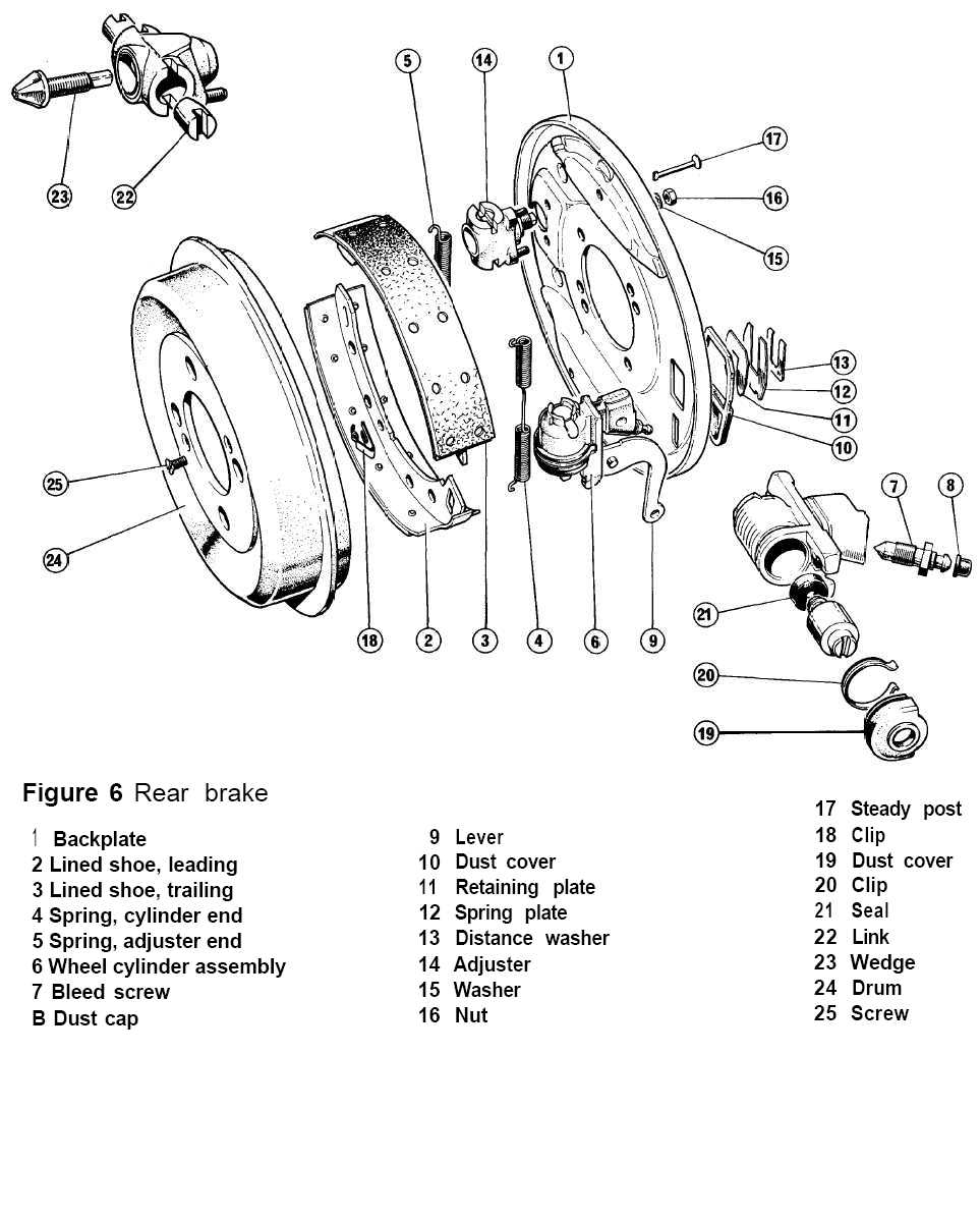
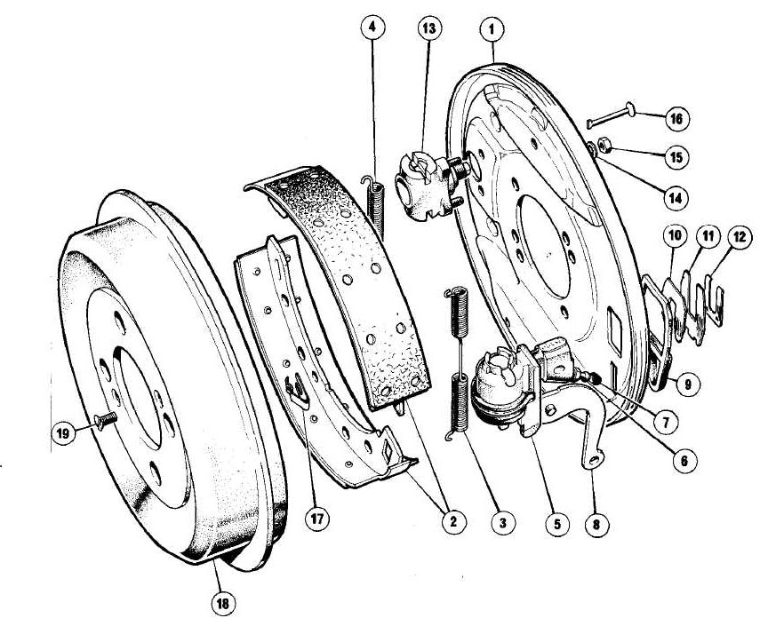
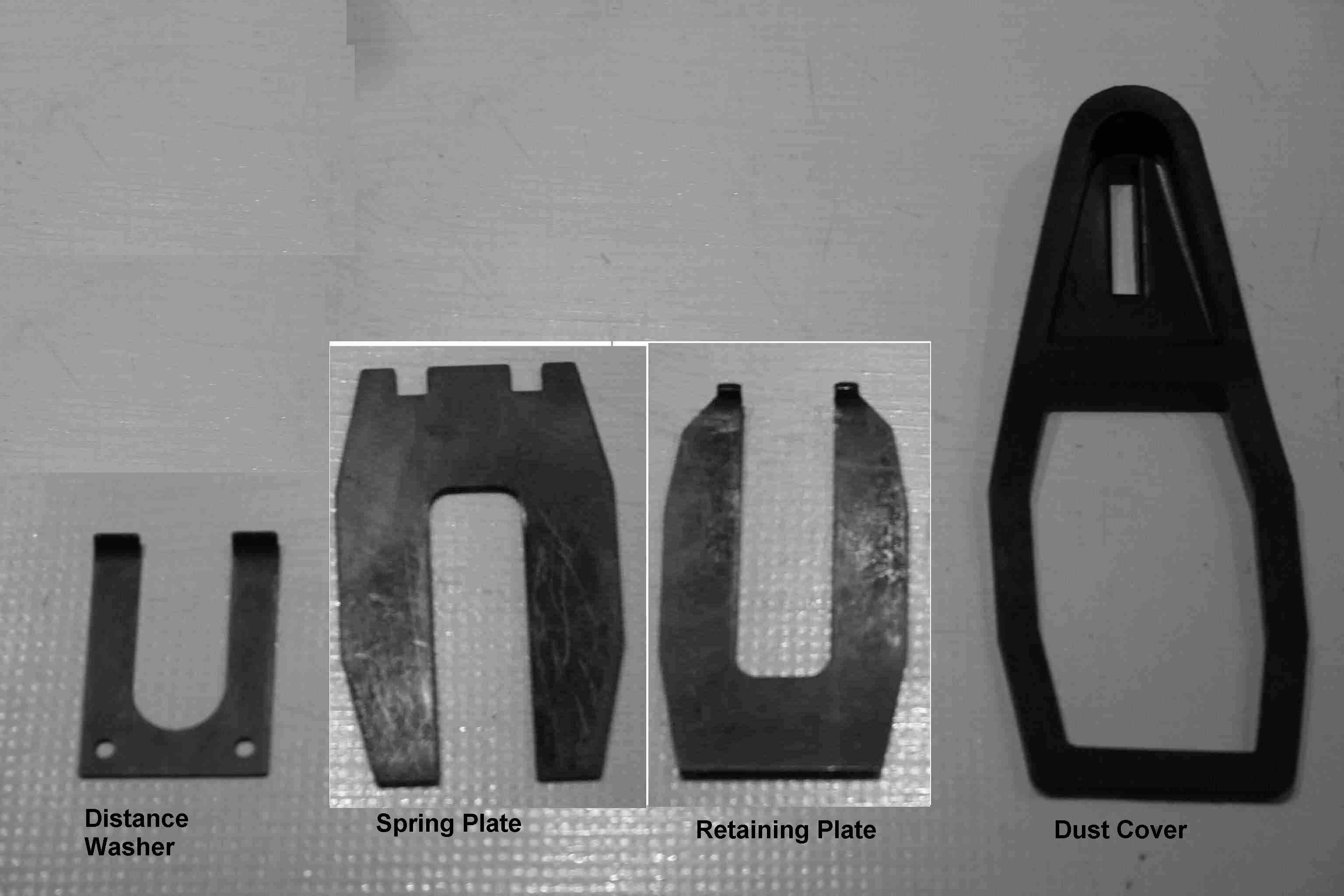
Next pics were not but should have been in the Handbook. Probably they're not in the handbook because every mecanic knew how to deal with this kind of brakes, that were used in almost all cars of that age |
||
|
|
|
|
|
|
|
|
Thanks Geoff |
||
|
Thanks James... James Couch provided a "brake excell" click |
||