|
Assembly
As
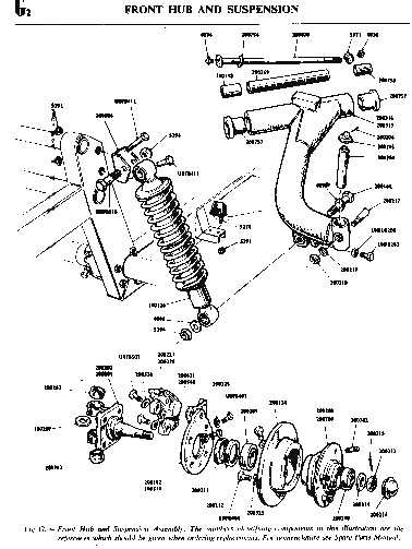
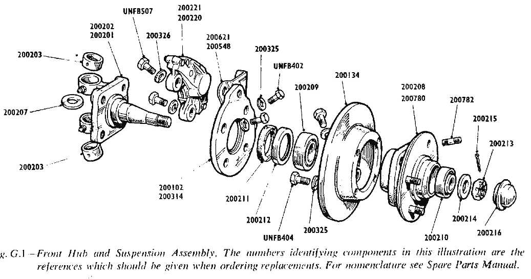
explained, it is necessary to dismantle and reassemble tbe front hubs every
5.000 miles. The following sequence is the correct method of assembly.
-
Both
inner and outer bearing and outer thrust rings are pressed into the end
spigots of the hub casting.
-
The
11 inch (27,9 cm.) diameter flanged disc-brake casting is then bolted to
the hub casting with four inch U.N.F. bolts, with spring washers.
-
The
stub axle is fitted with its felt seal, hub washer and the inner roller
thrust-bearing race. The bearing is greased liberally by hand; the felt seal
is temporarily removed (see 5. below).
-
The
brake caliper-plate is next secured to the stub axle. Note that these are
left and right handed) with 'L' and 'R' on the castings.
-
The
stub axle is then fed through the hub casting and the outer
roller-thrust-bearing race hand greased and fitted, followed by the 'D'
thrust washer, which keys to the axle thread flat.
The castle nut is fitted and tightened until there is resistance to free
rotation of the hub around the axle.
The nut is then released to the preceding castle slot which will accommodate
the split-pin through the stub axle thread.
The end of the stub axle and appropriate adjacent castellation of the nut
are centre-punched for future resetting.
Note that this setting for just-free rotation is best obtained with the felt
wasber seal (see 3 above) removed, as this offers resistance to free
rotation, which can mislead.
-
Remove
castle nut, withdraw stub axle for the final fitting of the felt seal, then
reassemble as above, finally securing the castle nut with the split-pin.
-
The
assembled hub is then mounted in the vice with the disc-brake flange
borizontal. Rotate the flange to check for rise and fall at its outer edge -
this must not exceed + 0,003' (0,08 mm).
-
The
outer domed grease cap is then tapped home on to its seat. The flanged rim
of the cap permits future removal by lift with a screwdriver tip.
-
The
appropriate brake caliper assembly -these are left and right handed, marked
'L' and 'R' is then bolted to the caliper plates simultaneously wilh the
hydraulic flexible hose bracket and any necessary shim washers, with two
-7/16 x 1-1/2 U.N.F. bolts and spring washers.
The gap must be
equalized between the caliper body and the brake disc flange to within 0,008'
(0,21 mm) and this is accomplisbed by packing the fixing bolts with 0,005"
(0,14 mm) shim washers.
Brake pads float
free retained by pins and slide clips.
The caliper body bas a rubber capped hydraulic bleed nipple, as well as the
brake hose connecting point.
|
|
-
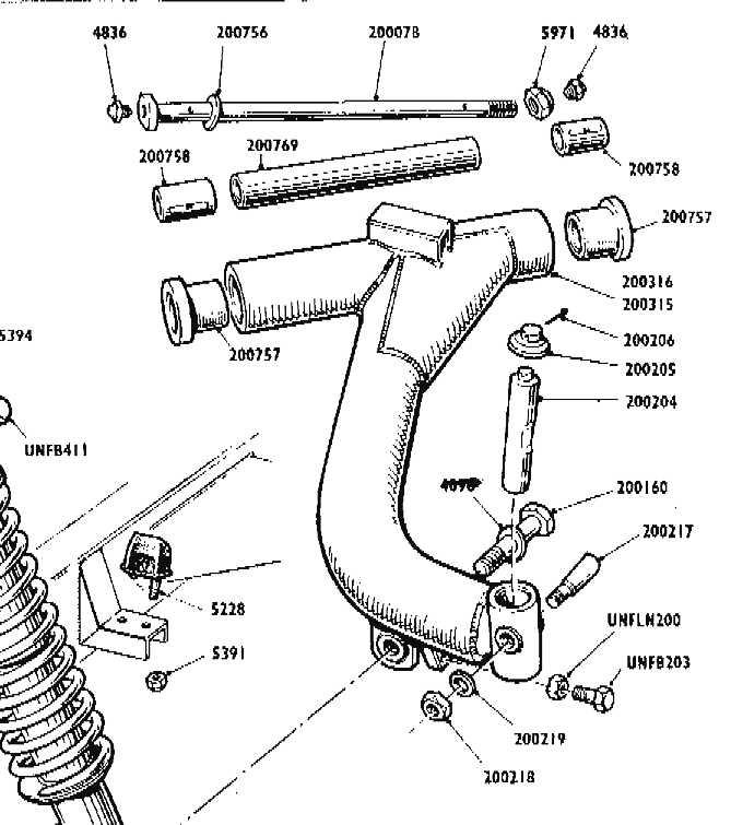
The
stub axle fork is fitted with two brass bushes which have helical grease
grooves, and two forward-facing grease nipples. The stub axle is attached to
the front of the radius suspension arm with a swivel 'king' pin fitted from
the top and secured with a cotter-pin and nut. A dust cap is fitted above
the swivel pin, and the steering arm keys into the slot in the casting
beneath the swivel pin
and is secured with two bolts and a bolt locking strap. Steering arms are
interchangeable.
Lubrication
To
obviate risk of over greasing of front stub axle bearings, no grease nipples
are fitted. It is necessary to dismantle the hubs every 5,000 miles, wash
bearings, re-grease with a lithium based grease and re-assemble, as above.
Greasing
should be liberal, but hub cavities must not be grease packed, as any emission
of grease will throw centrifugally and may grease the disc-brake flange and
impregnate the brake pads, with consequent loss of braking efficiency.
Bearing
Adjustment
Wear
of hub bearings is taken up, when necessary, by tightening of the hub castle
nut and refitting the split-pin.
This
will result in increased pressure exerted on the 'D' wasber and bearing races.
(see 5 above).
FRONT
SUSPENSION
General
Arrangement
Front
wheel stub axles are secured to the front radius suspension arms with swivel
pins and bushes.
These
tubular arms are, in turn, secured to the chassis with pivot pins
which are at an angle of 38°1/2 to the longitudinal axis.
The
pivot pin bushes are aligned for horizontal level with the chassis,
and end-play is limited by an internal spacing tube and washer, or
washers, to 0,009 inch (0,23 mm) maximum. This permits rise and fall of the
front suspension within limits of 2-1/2 inch (6,29 cm) bump and rebound -5 inch
(12,58 cm) total travel.
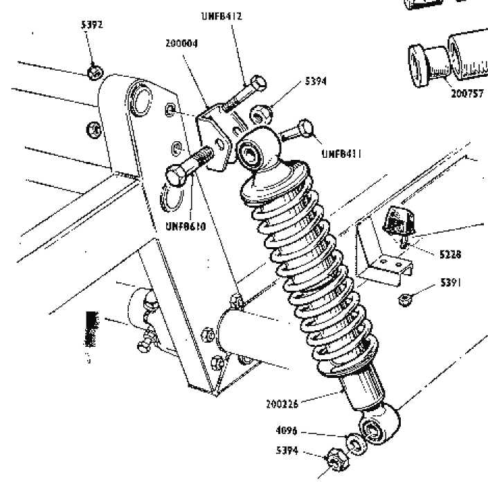
Suspension
Support
Independent
suspension of stub axles is augmented by independent springing. A heavy
coil-spring assembly, under compression, is fitted between the outer ends of
the radius suspension arms and the chassis main frame front head. These
springs enclose cylindrical hydraulic damping units which absorb shock loads
transmitted by the road wheels. There are rubber dome bump-stops fitted to the
chassis, beneath the suspension arms.
|
| H1
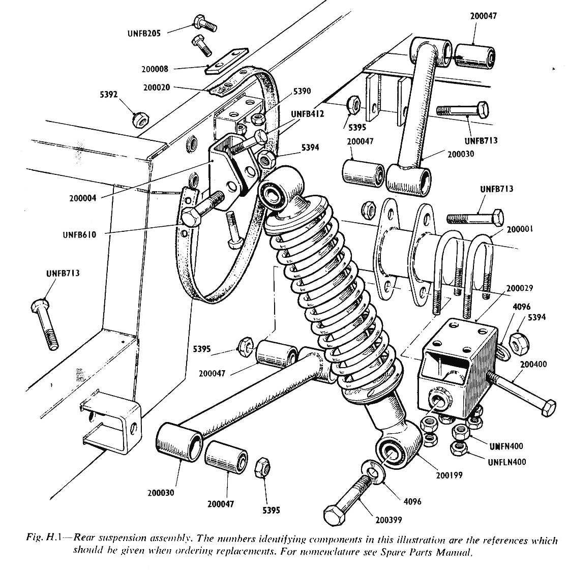
REAR SUSPENSION
A
simple arrangement uses hydraulically damped shock-absorbing cylinders
fitted with compression coil springs between the axle saddles and
high-mounted chassis brackets. Fore and aft alignement is
maintained by a |
|
modified Watt linkage with front and rear
radius arms between axle and chassis securing points.
Each end of each radius arm is rubber bushed,
eliminating need for lubrication.
Check straps are suspended around each side of
the rear axle from high-mounted chassis wing brackets, to limit rear
axle rebound or drop when jacking up the car. |