Section F (23/04/09 )
STEERING
F.1 General description and data
F.2 Steering wheel removal
F.3 Steering column removal
F.4 Removal of steering box, idler, dampers and track rods
F.5 Steering adjustments
F.6 Track arrangement
F.7 To adjust the track
F.8 Lubrication
|
||
|
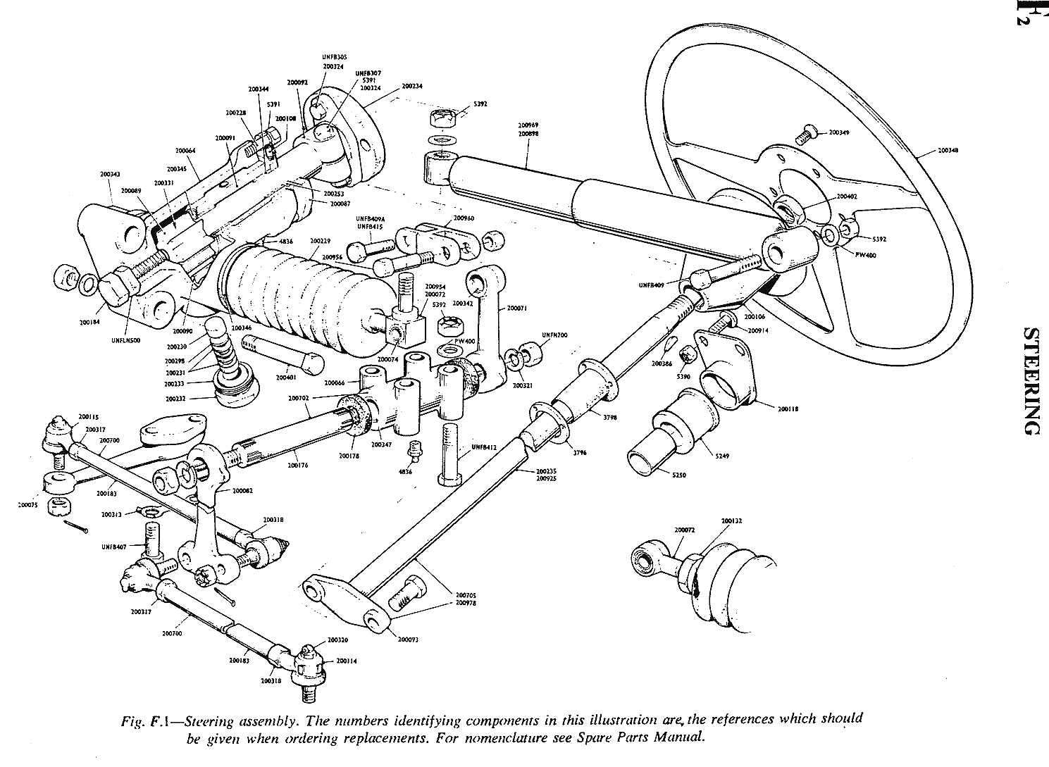
Fl GENERAL DESCRIPTION AND DATA The steering mechanism is of the rack and pinion type, movement being transmitted from the steering wheel and column, through the steering box and the idler levers to the track rods. Adjustments are made at the steering box and track rods. The l5 in. diameter wooden rimmed steering wheel is secured to the wheel boss by five countersunk screws; the boss is attached to the steering column by a castle nut with a plain washer, in addition, the boss and column are keyed. The column is supported by, and rotates in. a rubber guide with a phosphor-bronze bush, at the fascia panel and by an aluminium screwed plate on tbe engine side of the panel moulding. A flange on the end of the column connects with a silentbloc flexible coupling, to the steering box pinion flange, the assembly being secured by two bolts and selflocking nuts. In both the right and left hand drives, the components are similar, only the position of the steering box differs. On the right hand drive, the steering box is secured by three bolts and nuts to a bracket welded to the chassis forward frame and is mounted above and to the right of the steering idler. On the left hand drive, the steering box is secured by three bolts and nuts direct to the chassis frame and is mounted below and to the left of the steering idler. On the right hand drive, the steering box rack end is drilled horizontally, to be bolted to the idler link, and in addition, is drilled and tapped vertically. Provision is made for a steering telescopic damper, one end is bolted to the left hand side of the chassis, the other end is bolted to the vertical tapping in the rack end. The idler, mounted centrally, fore and aft, is secured by four bolts and nuts to a chassis cross member. The idler body retains the shaft, rotating in oilite bushes, to which the idler levers are splined. One lever is bolted to the idler link positioned above the idler, and the second lever, the drop arm, is double-ended to accommodate the track rod ends. On the left hand drive, the steering box rack has an eye end which is bolted to the idler link. The link is of U channel fabrication with a welded right-angled attachment; the second lever, the drop arm is also bolted to the idler link, the track rods etc. being identical to the right hand drive version. The steering telescopic damper is bolted to the link right-angled attachment, the other end of the damper being bolted to the right hand chassis frame. The track rods are Thompson type, tubular in construction with 'E' dual type ball joints at the steering arm end. The rods are adjustable either end, have right and left hand threads and are fitted with locknuts. Lubrication of the steering is via grease nipples at the following points. Steering box, two nipples, idler, one nipple, track rods, one nipple at each end of each track rod. It is recommende that these points be lubricated every 2,000 miles (3.200 kilometres). |
F2 STEERING WHEEL REMOVAL Remove the steering wheel cap from the wheel centre by inserting a lever and gently easing the cap out. Unscrew plain nut from the end of the steering column and lift off steering wheel and boss, collect Woodruff key from the steering column keyway. F3 STEERING COLUMN REMOVAL (Right Hand Drive) With the steering wheel removed to gain access to the flexible coupling and to facilitate column ------water bottle from its mounting. unscrew and remove the two bolts, nuts and washers securing the column flange flexible coupling and steering pinion flange. The column can now be eased forward from its support and guide bush until it is completely withdrawn. (Left Hand Drive) To enable complete withdrawal of the column, the steering box will have to be removed (see steering box removal below) before the column can be eased from its support and guide bush. The removal sequence, excluding steering box removal is identical to the right hand drive version.
. |
|
|
F4 REMOVAL OF STEERING BOX, IDLER, DAMPERS AND TRACK RODS To remove the steering box (right or left hand drive), flexible coupling previously disconnected, remove bolt securing rack end to idler link and disconnect the telescopic damper from the rack end (right hand drive only). Unscrew three bolts and nuts securing the steering box to the mounting bracket (right hand) or chassis frame (left hand drive) and lift off the steering box. To remove the idler, with the steering box previously removed, disconnect track rods from idler drop arm double end. Disconnect telescopic damper front idler bracket (left hand drive) and unscrew the four bolts and nuts securing the idler to the chassis cross member and lift off idler, complete with idler link. To remove the steering telescopic dampers, previously disconnected at the steering box rack end or idler link, unscrew the bolt retaining the damper to the chassis side frame and lift off the damper. To remove the track rods, not previously disconnected at the idler drop arm, remove split pin and nut from the track rod and steering arm attachment. Exert pressure upwards on track rod, support the steering arm end and tap opposite side sharply releasing the track rod from the steering arm.
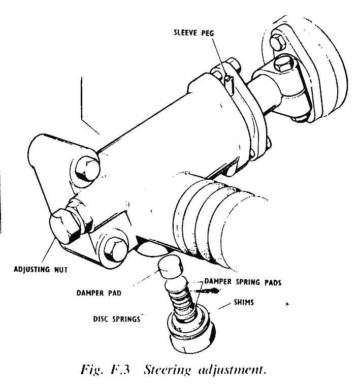
F5 STEERING ADJUSTMENTS Adjustments are carried out at the steering box and track rods. For slack or loose steering, slacken off the two selflocking nuts with sleeve retaining plate. Tap eccentric sleeve peg to turn sleeve (thus taking up any backlash between rack and pinion). Tighten self-locking nuts. Pinion end play (column end play) is taken up on the pinion adjusting nut on the steering box casing. Should there be any play in the rack, the damper plug on the underside of the steering box should be removed and the cup springs, spring pads and shims inspected. To increase compression against the track, remove shims as required from damper plug. Should there be play on the idler shaft, renew the two oilite busbes. Check on end splines of shaft and mating splines of idler arms. Renew if defective. Should the steering column be bent, it must be renewed. F6 TRACK ARRANGEMENT The 'toe-in' of front road wheels (0,218 in.) is set by two track rod tubes which run to the front stub-axle steering arms, from either side of the central steering-idler box. The idler box drop arms impart turning push-pull effort to the axles. !!Elsewhere is stated: toe-in 1/16 in or 1,5mm !!
|
F7 TO ADJUST THE TRACK 1. Jack up the front of the car. 2.
Free the locknuts at each end of the two track-rod tubes. 3. Rotate the track-rod tubes by hand, or pipe-grip-forwards at the top to reduce track width, rearwards at the top to increase track width. 4.
Equalize the settings of the two track-rod tubes by checking the
thread lengths left in view. To check that equal adjustment has been
obtained, throw the steering wheel alternately to full right, then to full
left lock, and see that full travel is obtained either way. 5. Tighten the locknuts. 'Toe-In' Adjustment Because of the effect of weight on the attitude of the front wheels, the car should be loaded (two persons or equivalent) to all up weight, before making final adjustments. Checking for Wear When excessive wear has taken place between the swivel pins and bushes, it may be apparent in uneven wear of the front tyres. To check for excessive wear, jack up the front of the car until the wheels are clear of the ground, then, taking hold of the top or bottom centres of the wheels, rock them about their fore and aft axes; this will disclose visible movement between the stub-axle forks and the ends of the radius suspension arms, if wear has taken place.
|
|
|
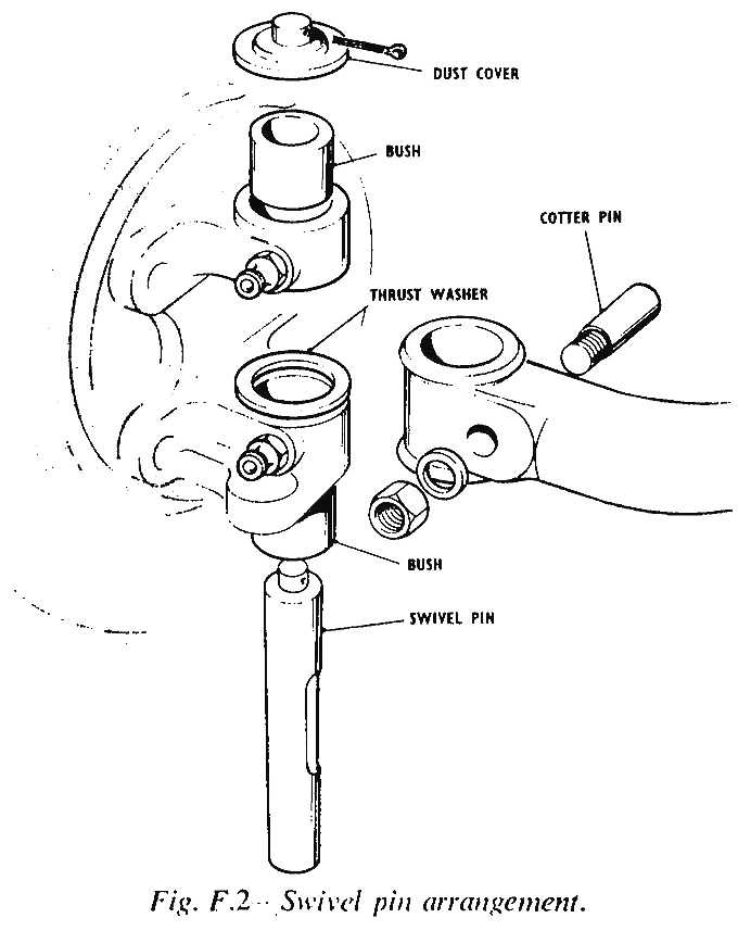
To Replace Swivel Pins and Busbes The following procedure should be adopted for the replacement of swivel pins and bushes on either side of the car:
|
7. Remove the two front grease nipples from the stub-axle forks and, with the aid of a piece of steel tube slightly smaller in diameter than the stub-axle fork bushes, drive the worn bushes out of the forks. (If these are difficult to shift, heat the forks a little with a blowlamp). 8. Fit replacement bushes, heating the stub-axle forks if necessary and taking care that the helix aperture lines up with the grease nipple inlet holes inside each bush. Refit the grease nipples. 9. Check the replacement swivel pins in the newly fitted bushes ease the busbes with an expanding parallel reamer until the pin is a slide fit. 10.
Reassemble, working back through these points. F8 LUBRICATION There are five lubrication nipples in the steering idler and track rod system and these require periodic greasing. Two are on the steering arm/track joints, two on the idler arm/track joints, and one is beneath the steering idler top mounting pivot. |
|
|
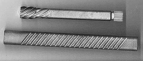
Note: The shape of the rack and pinion (as shown in the figure on top of
the page) is not correct.
This is what they should look like:
|
||