Section E (24/12/08 )
CLUTCH
E.1 General
E.2 Clutch adjustments
E.3 Pedal adjustments
E.4 The clutch operating cylinder
E.5 The clutch master cylinder
E.6 The pedal assembly
E.7 Overhauling the clutch and release mechanism
E.8 The clutch release bearing
E.9 The clutch pilot bearing
E.10 Specifications and repair data
|
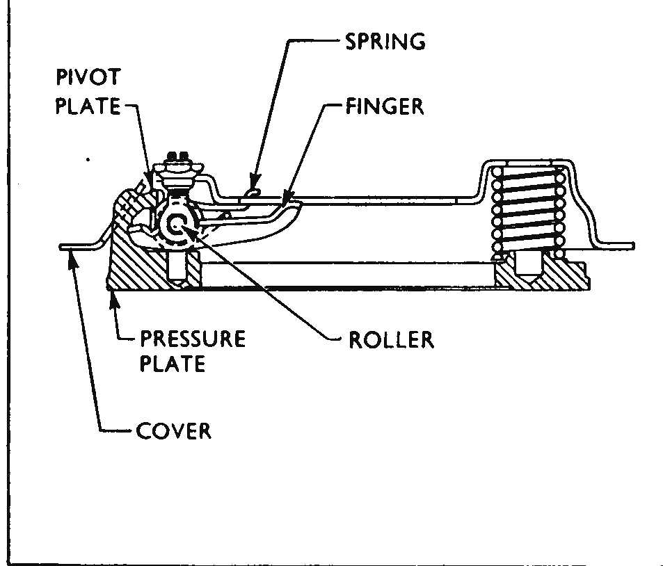
E1 GENERAL The clutch assemblies are of the single dry plate type 8,5 in. (215,9 mm) diameter. The clutch disc incorporates a spring-cushioned hub; the woven asbestos linings are flexibly mounted to ensure a smooth take-up of the drive. The clutch disc hub is free to slide along the splines of the main drive gear, the forward end of which forms a spigot to fit into the clutch pilot bearing in the centre of the flywheel. The clutch cover, springs, clutch release mechanism and pressure plate are serviced as an assembly. At the release finger pivot points there is only rolling contact, sliding friction is eliminated. The clutch release mechanism is hydraulically actuated by means of a pendant pedal mounted beneath the instrument panel, controlling the clutch master cylinder. A pipeline and flexible hose connects the master cylinder to the operating cylinder mounted on the clutch housing and retained by means of a circlip. Any possibility of irregular clutch engagement caused by movement of the engine, clutch and gearbox unit in relation to the clutch pedal is therefore eliminated. Maintenance The clutch fluid reservoir is integral with the clutch master cylinder and the level should be checked every 1,000 miles. Top-up with genuine brake fluid to the level marked on the outside of the reservoir casing (see Fig. E.3), which is approximately 1 in. (16 mm.) from the top. The cap and reservoir should be wiped with a clean rag before removing the cap to ensure that no dirt or foreign matter enters the system. Make sure that the vent is clear before replacing cap. The only other attentions which may be required by the clutch mechanism are the adjustments described as follows:
E2 CLUTCH ADJUSTMENTS When the clutch mechanism is correctly adjusted the following conditions apply: 1. Just perceptible clearance between the pedal push rod and master cylinder piston. 2.
1/16 in. (1,6 mm.) clearance between the clutch release arm and the
operating cylinder push rod. |
E3 PEDAL ADJUSTMENT The pendant clutch pedal is linked to the master cylinder piston with an adjustable push-rod, with clevis attachment to the pedal shank. The push-rod has an adjustment nut with lock nut and these are positioned and locked together to correct pedal travel, as necessary. The pedal pad is also adjustable, at its mounting point at the foot of the pedal shank. The clearance between the clutch release arm and operating cylinder push rod should normally be 1/16 in. (1,6 mm.), although on a new car or after a new clutch disc has been fitted, the clearance should be increased to 1/10 in. (2,7 mm.). Should the clearance at this point be reduced, it is possible for the clutch release bearing to be in permanent contact with the clutch-fingers, causing unnecessary wear and possibly clutch slip. To effect the adjustment, disconnect the retracting spring, slacken the lock nut and turn the domed adjusting nut until the correct clearance is obtained between the end of the release arm and the nut. Tighten the lock nut securely, recheck the adjustment and reconnect the retracting spring.
E4 THE CLUTCH OPERATING CYLINDER The clutch operating cylinder is mounted in the flange of the clutch housing on the right-hand side and is held in place by a circlip.
1. Disconnect the retracting spring. 2. Using a pair of circlip pliers, remove the retaining circlip. 3. Withdraw the cylinder assembly forwards complete with push rod. 4. Remove the push rod and the dust excluding rubber cap. Gently depress the clutch pedal to push the piston and seal out of the cylinder. 5. Disconnect the flexible hose and fit a blanking plug to the hose to prevent fluid loss. Note.-Should it be necessary to remove the cylinder complete without dismantling it as described, a pump applied at the fluid union can be used to push the piston and piston seal from the cylinder.
To Dismantle 1. Remove the bleed valve from the cylinder. 2.
Pull the rubber piston seal off the spigot at the front of the
piston. |
|
|

|
|
|
of damage to the sealing lip. Never use mineral fluids such as engine oil or paraffin for washing hydraulic system parts.
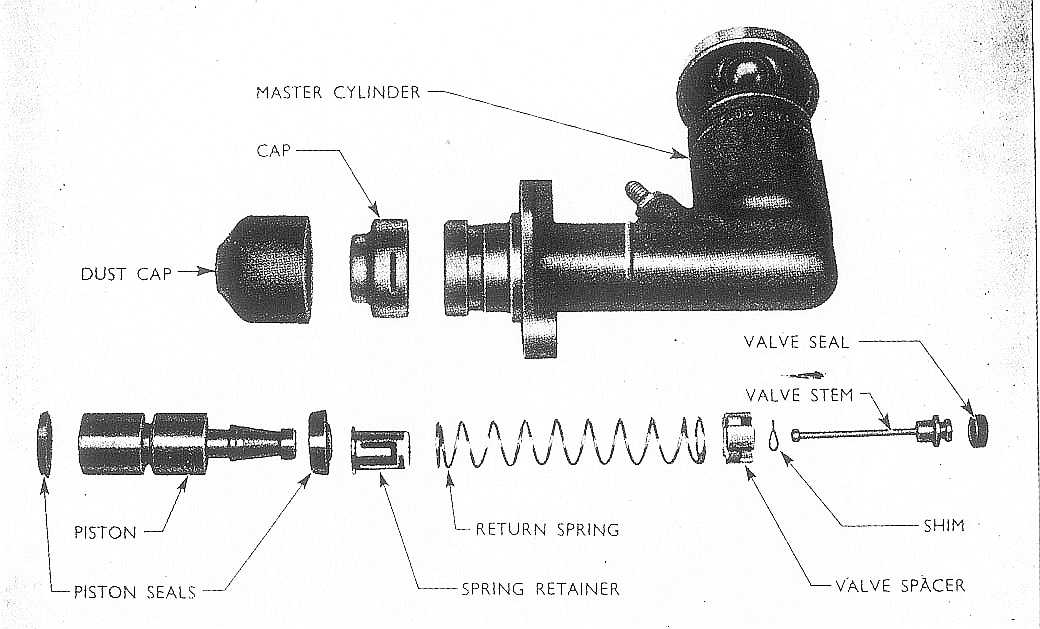
1. Locate the piston seal on the spigot at the front end of the piston so that the sealing lip is away from the body of the piston. 2. Dip the piston and seal in hydraulic fluid and carefully insert, spigot end first, into the cylinder. 3. Refit the rubber cover over the end of the cylinder. 4. Replace the bleed valve in the upper of the two unions but do not tighten. To Replace 1. Remove the blanking plug from the end of the flexible hose and reconnect the hose to the cylinder. 2. Replace the push rod and slide the cylinder into its location on the clutch housing flange from the front. Replace the circlip and ensure that it locates correctly in its groove. 3. Bleed the hydraulic system as described on page M.6. 4. Adjust the clearance between the domed nut on the operating cylinder push rod and the clutch release arm as described previously. E5 THE CLUTCH MASTER CYLINDER The clutch master cylinder is mounted on the engine bulkhead and is bolted to the front flange of the pedal assembly bracket.
|
The front spigot end of the piston accommodates the
valve stem and carries the return spring retainer. The return spring
(under compression) is fitted between the spring retainer and valve spacer
at the forward end of the cylinder (see Fig. E.3). A valve seal is fitted
to the forward end of the valve stem. From approximate engine Nos.
204E-140540 and 206E-132253, an improved type of seal incorporating an
annular ring moulded on its outside periphery is fitted. This modified seal should be fitted in place of the
previous plain seal if a replacement is required in service. A reservoir port drilled at the front of the cylinder
allows fluid from the integral reservoir to enter the cylinder. The pipe
line to the clutch operating cylinder leaves the master cylinder at a port
immediately behind the reservoir. When the clutch pedal is in the fully
released position, fluid is free to flow from the reservoir into the
cylinder. When the pedal is depressed the piston moves forward and closes
the valve to prevent the fluid being pumped back into the reservoir. The
fluid is therefore pumped through the outlet port to the operating
cylinder on the clutch housing. When the pedal is once again released the
return spring pushes back the piston, reducing pressure in the cylinder,
and the release arm retracting spring acting on the operating cylinder
piston pushes the fluid back into the master cylinder. The valve uncovers
the reservoir port so that fluid may be replenisbed in the cylinder as
necessary. A rubber cap fits over the end of the master
cylinder and fits closely around the push rod to prevent the entry of dirt
into the cylinder. The clearance between the push rod and the piston on the cylinder is pre-set and the piston cannot be prevented by the push rod from returning to its full extent. |
|
|
||
|
E6 THE PEDAL ASSEMBLY The clutch pedal is of the pendant type, secured at its top by a pivot bolt and connected to the master cylinder with an adjustable push-rod.
1. Remove the clevis pin which connects the push rod clevis to the speclal shank. 2. Release loading spring. 3. Remove the top pedal pivot bolt and anti-rattle spring. 4. The assembly may now be manoeuvred downwards, and freed. Reverse this procedure to refit, taking care to replace the anti-rattle spring.
1. Remove the clutch shank clevis pin from the push-rod. 2. Disconnect the hydraulic pipe union from the cylinder body. 3. Remove the two bolts securing the cylinder body to the rear engine bulkhead. 4. Remove cylinder complete with push rod, and drain. Reverse procedure to refit, taking care to re-set the pedal adjustment to give 'just perceptible' movement before engaging the master cylinder piston stroke. |
E7 OVERHAULING THE CLUTCH AND RELEASE MECHANISM To gain access to the clutch, the gearbox or engine must first be removed.
|
|
|
|
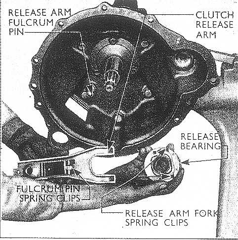
7. To dismantle the clutch release bearing assembly, hold it with the bearing downwards and tap the shoulder of the hub sharply on the bench. 8. Reassemble the clutch release bearing. Check that the release arm fork spring clips on the rear face of the hub (illustrated in Fig. E.1) are in good condition and assemble the new bearing on the hub with the thrust face of the bearing away from the hub. Suitably support the bearing on the bed of a press, leaving sufficient clearance for the shouldered end of the hub to protrude. Press the hub into position, ensuring that it enters squarely into the bearing bore. 9. Pass the clutch release arm through the aperture at the side of the clutch housing, with the fulcrum pin spring clips, shown in Fig. E.1, facing towards the rear. Engage the clips around the fulcrum pin load. 10.Check the machined sleeve of the gearbox main drive gear bearing retainer for burrs. etc., lightly smear the sleeve with high melting point grease and replace the release bearing assembly, engaging the forked end of the release arm in the spring clips on the hub. Check that movement on the outer end of the release arm is freely transmitted to the bearing. Refit the rubber gaiter to the clutch release arm. 11.Replace the gearbox or engine whichever has been removed.
THE CLUTCH RELEASE BEARING Care
must be taken during service, that the correct clutch release bearing hub is
fitted. Clutch release bearing hub Part No. EOA-7561 differs from the hub
Part No. 204E-7561 by the length of the machined surface from the front face
of the hub to the shoulder which abuts the rear of the release bearing. 1. Remove the gearbox assembly as described in section C. Where a rubber gaiter is fitted on the clutch release arm, detach the outer clip and pull the gaiter off the arm. 2. Pull the forked end of the release arm out of the spring clips at the rear of the bearing hub and disengage the arm from the fulcrum pin. Pull the hub and bearing off the main drive gear bearing retainer. |
|
|
3. Hold the release bearing assembly with the bearing downwards and tap the shoulder of the hub sharply on the bench, when the bearing can be removed from the hub.
E9 THE CLUTCH PILOT BEARING This bearing serves as a mounting for the forward end of the main drive gear and only rotates relative to the main drive gear when the clutch pedal is depressed. The bearing is of the sintered bronze type and it is most important that it is fitted square in its bore in the flywheel with the shouldered face towards the engine and the flat face towards the clutch. Alternatively, a ball type clutch pilot bearing (B-7600-A) is available for service only, together with a 0,004 in. (0,10 mm.) oversize ball bearing. |
A noise, audible when the clutch is fully depressed, does not necessarily indicate that the pilot bearing is at fault, since the clutch release bearing itself is also rotating on the hub under these conditions. In the event of a noise associated with either the clutch release bearing or the pilot bearing, the following test will enable the sound to be located. Press down the clutch pedal with sufficient pressure to cause the release bearing to rotate without freeing the clutch. If the sound is then heard, the noise is definitely associated with the release bearing. If the noise increases when the clutch is fully depressed, then the additional noise may be due to a worn pilot bearing in which case it should be replaced.
1. Remove the gearbox assembly as described in the 'Gearbox' section. 2. Remove the clutch disc and pressure plate as described on page E.4. 3. Withdraw the bearing from the flywheel, using Tool No. AT3/U7600-A. If the pilot bearing is being removed from the flywheel on the bench, the driver AT/U7600-B may be used to press the bearing from its flywheel location.
1 Locate the new pilot bearing in its location with the flat face of the bearing towards the clutch disc and the shouldered face towards the engine. 2 Tap the bearing into place. using the driver AT/U 7600-B, ensuring that it is fitted square in its bore. This latter point is most important, as an incorrectly fitted bearing will quickly wear and cause clutch noise and vibration. 3 Replace the clutch disc and pressure plate assembly as described on page E.4. 4 Replace the gearbox as described in section C. E10 SPECIFICATIONS AND REPAIR DATA Clutch disc linings:
Pressure
springs: 6 - brown
with blue paint mark
|
|