|
| |
Section D (24/12/08
)
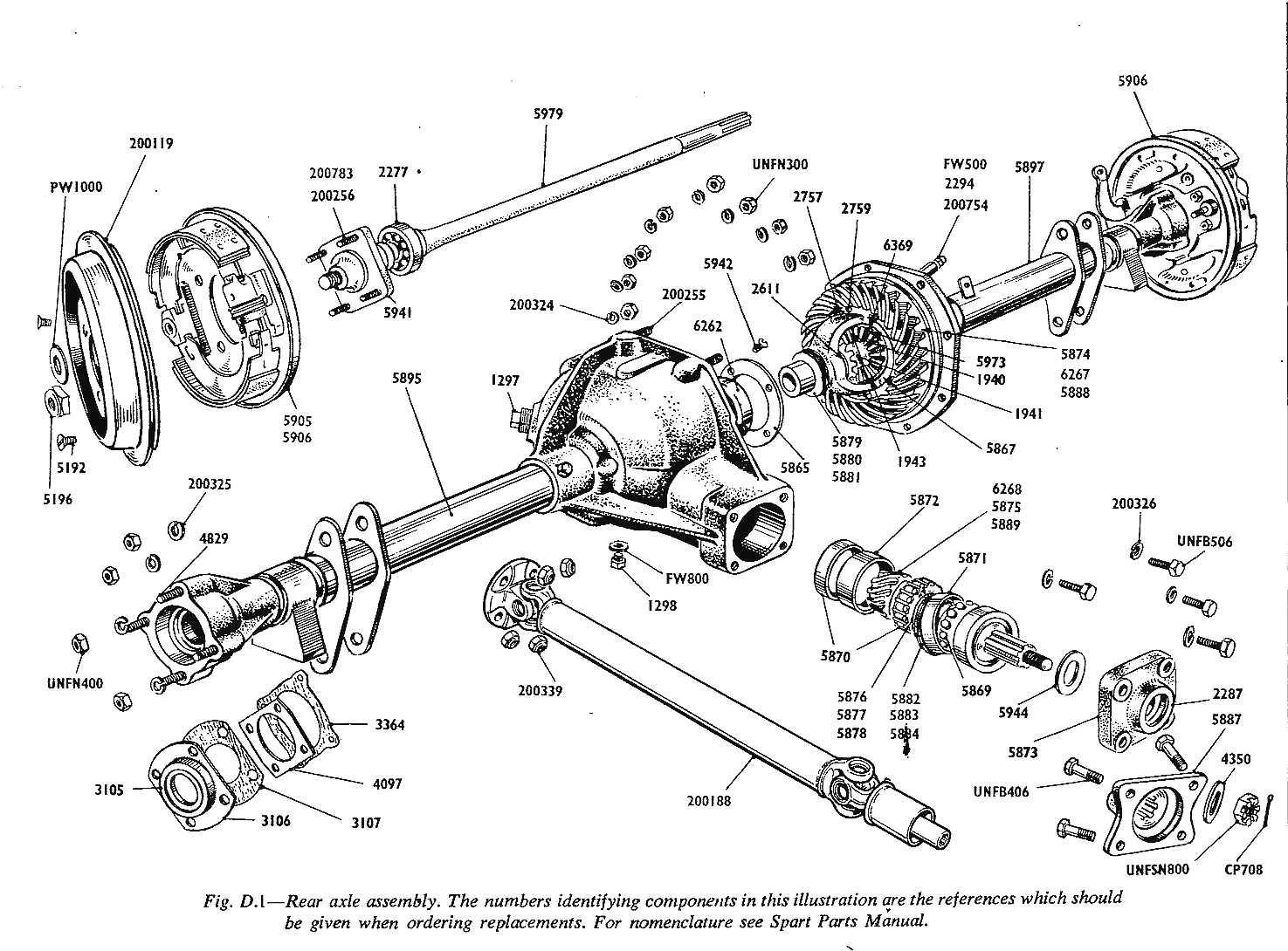
REAR AXLE AND PROP SHAFT
D.1 To remove rear axle from car
D.2 To refit the rear axle
D.3 To dismantle the axle
D.4 To reassemble the axle
D.5 To reassemble the pinion body
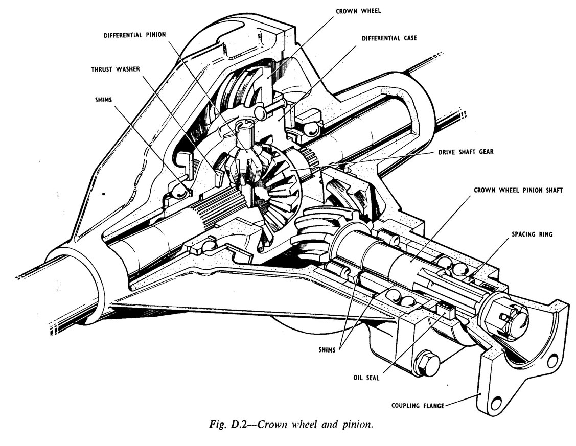
D.6 To mesh the crown wheel and pinion
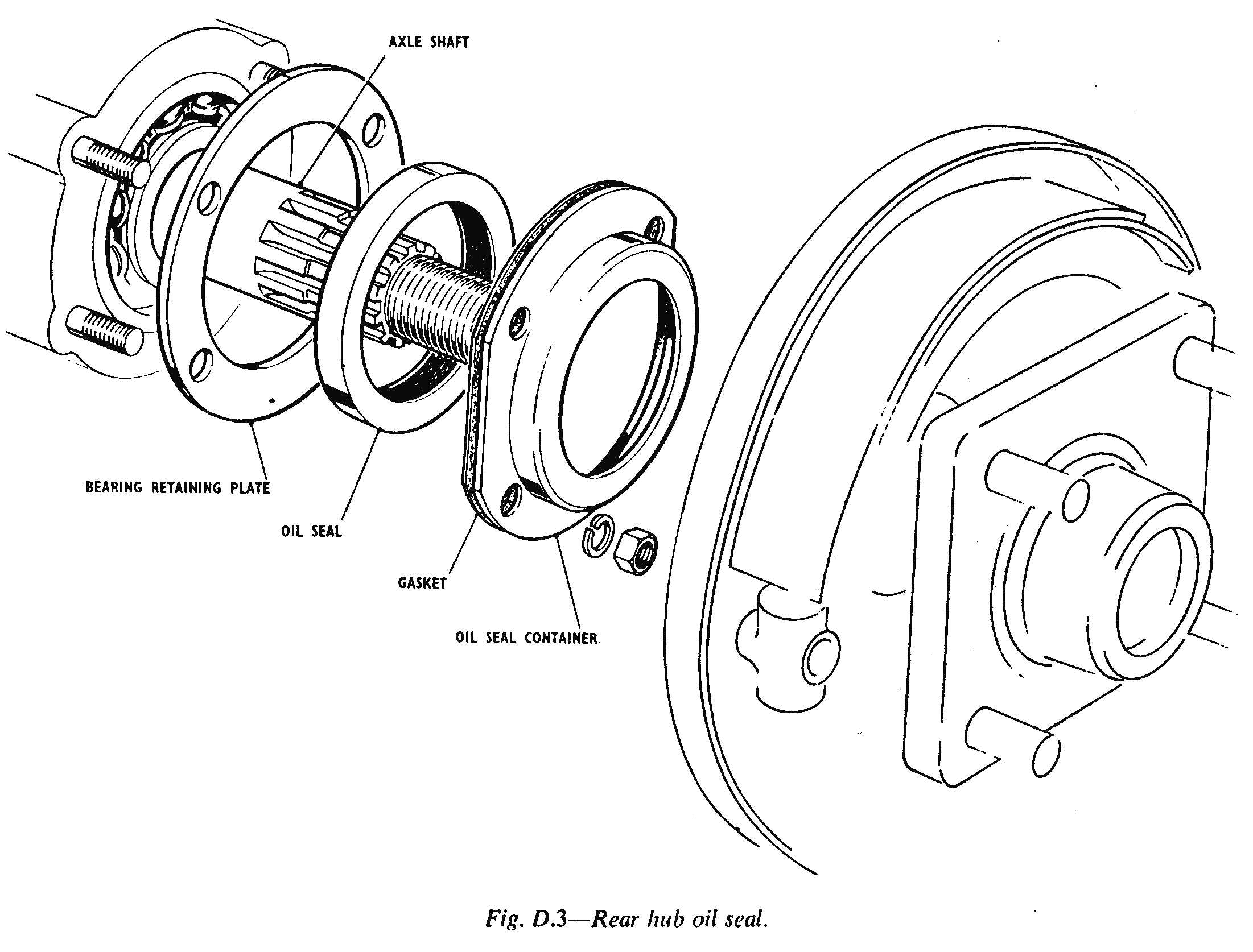
D.7 To replace a rear hub oil seal with axle in the car
D.8 Propeller shaft
| |
|
|
Dl
TO
REMOVE REAR AXLE FROM CAR
-
Jack up the rear of the car and support the chassis on stands, so that the
rear wheels are clear of the ground. The rear axle will then be suspended
and held by the two check straps.
-
Remove the rear road wheels.
-
Disconnect the hydraulic brake hoses and the hand brake flexible cable.
Remove the hand brake cross rod by split-pin and clevis disconnection.
-
Remove bolts and nuts to free the two radius arms from the rear axle tube
lugs, at each side.
-
Remove the four bolts and self-locking nuts from the propeller shaft
coupling.
-
Free the hydraulic suspension units from the rear axle saddles, at each
side.
-
Support the axle at each side, and remove the two check straps from their
top brackets. The axle can now be removed.
|
|
D2
TO
REFIT THE REAR AXLE
Reverse
the above procedure.
D3
TO
DISMANTLE THE AXLE
-
Remove the level and filler plug and drain plug, to drain rear axle oil.
Incline the axle laterally, first one side high then the other, to leave
as dry as possible.
-
Remove the two brake drums by withdrawing the two countersunk screws, at
each side.
-
Remove the rear shaft lock nuts, end washers and hubs.
-
Remove the four 1/2 U.N.F. nuts, spring washers and brake plates, complete
with shoes, from each side.
-
Take off the rear oil seals, gaskets and bearing retaining plates.
-
Withdraw the rear half-shafts.
|
|
|
|
|
-
Remove
the eight nuts and spring washers from the perimeter flange of the
axle plate and knock the two halves apart with a hide mallet.
Note that the rear axle tubes are welded to the axle plate and axle
case from inside, and can only be freed by turning away the weld seam
in a lathe. They are
press fitted and bolt retained in the axle end castings.
Splitting of the axle case will, in this way, expose the differential
case and inner bearing.
The hand brake cross rod bracket will come free from its mounting to
the two rear axle case studs. A vent pipe is fitted to the top of the
axle case and can be turned with a pipe grip, to unscrew and remove.
There is an additional 3/32' diameter oil breather hole in the left
hand axle tube and this should be cleaned out, as necessary.
There is no gasket between the axle case and axle plate and the
spigoted joint is dressed with shellac only, to preserve the oil seal.
-
Remove
the crown wheel assembly complete from the plate, using a pair of
levers bearing against the plate to withdraw the crown wheel hub from
its bearing.
Note that there are shims on the crown wheel hub which have been
fitted to set the position of the crown wheel in transverse relation
to the pinion drive gear. These shims will be either 0-010', 0-005' or
0-003' thick.
-
Dismantle
the planet gear assembly by straightening the end retaining pegs. This
will free the differential pin, spur gears and drive shaft gears. The
latter are multi-splined in the bore to convey drive to the axle
half-shafts, which float in them. The drive shaft gears are backed
with brass thrust washers which have concentric oil grooves on each
face. The two differential spur gears have brass thrust washers which
are crowned, but not grooved.
-
Remove
the pinion body and dismantle this, if required, by withdrawing the
splitpin, castle nut and pinion. To do this, key the coupling flange
temporarily to the pinion body with a steel peg through one of the
propeller shaft securing holes, so that the nut can be undone.
-
Drive
the pinion out, using a drift to bear on the end of the pinion
gear.
-
The
inner and outer bearing races, spacers and the pinion end washer can
then be removed. Note that shims have been fitted to space pinion
bearings correctly.
|
|
D4
TO
REASSEMBLE THE AXLE
Reverse
the dismantling procedure but take note of the following points relating
to pinion assembly and meshing of crown wheel and pinion.
D5
TO
REASSEMBLE THE PINION BODY
-
Fit
the roller bearing inner race by pressing on to the pinion shoulder,
just in front of the pinion teeth.
-
Fit
the centre spacing tube.
-
Replace
the shims. These normally aggregate 0-018' total thickness.
-
Fit
the double thrust ball race which has a dual track brass cage, with
separate outer races.
-
Fit
the roller bearing, outer race, to the pinion body casting-pressed
home on to the spigot seat.
-
Fit
the outer spacing ring.
-
Insert
the assembled pinion aid, using tallow to coat the body sleeve, tap
the double ball thrust race down; working around this carefully to
ensure true alignment to the sleeve. The pinion will be 'home' when the race is approximately 1/2" proud, above the end of the
pinion body casting.
-
Fit
the pinion bearing cover cap with a spring radial rubber oil seal. A
shim ring inside the cap will bear on the outer bearing race-0-003',
0-005' or 0-010' thick shims will have been used in original works
assembly, as necessary, so that the cap is 0-003' clear of the body,
to give positive grip of the assembly when the cap is bolted down.
-
Coat
the cap face with shellac and secure with four 1 1/4 x 7/16
"U.N.F. bolts, and spring washers.
-
The
rear axle coupling flange is then greased and fitted, through the oil
sealing ring, on to the pinion spline; followed by a flat washer,
castle nut and splitpin. Use the steel peg, previously described, to
temporarily key the flange, whilst tightening the nut.
D6
TO
MESH THE CROWN WHEEL AND PINION
Check
pinion and crown wheel back-lash by to-and-fro hand movement of the
coupling flange. Fit the right hand half-shaft temporarily and turn this,
listening through the axle-case vent hole, to the sound of the pinion and
crown wheel as they rotate, dry. Back-lash should be just perceptible and
rotation, as described should not produce any harsh 'chatter' from the
gears. |
|
|
|
|
|
The
pinion nut can be re-set either slacker, to let the pinion IN-, or tighter, to move it OUT.
The crown wheel hubs are shimmed so that variation in these shims and in
the IN or OUT setting of the pinion, will determine the mesh of the crown
wheel and pinion.
A visual check of mesh is obtained by coating the crown wheel and pinion
teeth with Markers' Blue or with a flat, undercoat paint. Following the
hand rotation described, it will be seen that the Markers' Blue or paint
has been partially extruded from between the teeth, where they engage, to
leave clean metal.
When correct mesh is obtained, this should occur in the centre section of
each tooth so that tooth 'heel' and 'toe' marking only is left.
D7
TO
REPLACE A REAR HUB OIL SEAL WITH AXLE IN THE CAR
-
Jack
up the appropriate side.
-
Remove
the road wheel.
|
|
-
Disconnect
handbrake cross-rod clevis.
-
Remove
axle shaft lock nut and washer.
-
Remove
brake drum countersunk screws and drum.
-
Remove
the four 1/2" U.N.F. nuts, spring washers, brake plate and
gaskets. The oil seal and bearing retaining plate will follow.
-
Fit
the new oil seal and reverse the above procedure, to reassemble.
D8
TO
REPLACE THE PINION OIL SEAL
-
Mount
the car on a lift platform, or over a pit.
-
Remove
the four propeller shaft bolts and nuts from the axle couple flange.
-
Centre
dot the castle nut and pinion spindle. Remove the split-pin and castle
nut and take off the flange.
-
Remove
the four 7/16" U.N.F. bolts and spring washers securing the
pinion bearing cover cap. Take off the cap.
|
|
|
-
The cap is fitted with shims and the sprung radial rubber oil sealing
ring, in its bore. Press the seal out and replace.
Reverse
the procedure to reassemble, greasing the pinion bearing cover cap to aid
bedding on to the bore of the new oil
seal. Re-align the castle nut and spindle centre dots-
see 3 above - to re-set crown wheel and pinion mesh
correctly.
D9
PROPELLER
SHAFT
-
Make
The complete propeller shaft unit is a standard manufacture by Hardy
Spicer Limited.
-
Drive
There is a front spline-socket which is fitted through the gearbox
rear cover cap and radial seal ring, to engage on
|
|
the
gearbox main shaft. This socket runs in the white metal bush inside the
rear cover. Fore and aft movement transmitted from the rear axle is
accommodated by the socket splines, which are a slide fit on the gearbox
main shaft.
-
Features
The propeller shaft has a double yoke universal joint at each end,
with the yoke forks pivoting in spring-clip retained needle bearings.
-
Lubrication,
Wear
There is a grease distributing nipple projecting from each yoke
assembly and this distributes grease to the four needle bearings at
each end of the propeller shaft.
A manual check will disclose any side play on spline or yokes, to
indicate wear and to assertain need for replacement of bearings or
propeller shaft.
-
Rear
Axle Fitting
The propeller shaft has a rear coupling plate with four holes to
accommodate bolts and self-locking nuts, for the transmission of drive
to the rear axle differential coupling.
|
|
|
|
|
Common Technics
|