GENERATOR OUTPUT CONTROL
The main characteristic of the plain shunt
connected generator is that the output rises with increasing speed and if this
were uncontrolled irreparable damage would be caused to the generator and the
battery.
The systems currently used to control this
output are:
1. Compensated Voltage Control
2. Current-Voltage Control.
COMPENSATED
VOLTAGE CONTROL
It will be remembered that battery terminal
voltage varies with the state of charge, so if we control the voltage of the
generator at a specific level i.e. terminal voltage of a fully charged battery,
then the pressure differential between the generator and the battery will be
greatest when the battery is discharged allowing a high current to flow,
reducing as the battery becomes charged, until theoretically the pressures will
be equal and no current will flow,
If the battery was in a very low state of
charge, the current flow could be extremely high, most probably higher than the
generator could safely deliver, and the armature windings would be damaged.
Because of this, we have to use some form of COMPENSATION.
At low speeds, the generator output is less
than the battery voltage, so an automatic switch or cut-out is incorporated in
the circuit to prevent the battery being discharged through the armature
winding.
COMPENSATED
VOLTAGE CONTROL
RB.
106 LUCAS
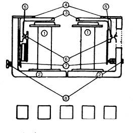
Fig. 1
Fig.
1 shows a section through the RB106, and from this we can trace its build-up
and operation.
Two
soft iron cores (Fig. 1-1) are mounted
on an 'L' shaped soft iron frame (Fig. 1-2). (For simplicity, the frame
is shown in two parts)
An. ‘L’ shaped armature (Fig. 1-3) carrying a contact Point (Fig. 1-5) is mounted above each core on a spring
blade (Fig. 1-4).
This
contact is so positioned to line up with a stationary contact (Fig. 1-6)
insulated from the frame. Another spring blade (Fig. 1-7) is attached to the vertical arm and lines up with fine
threaded screws (Fig. 1-8), which
can be adjusted to vary the force required to move the armature.
You will see that the L/H points are held
in the closed position by the spring blade (Voltage Regulator) and the R/H
points are held open by the spring blade (Cut-out).
REGULATOR
POINTS
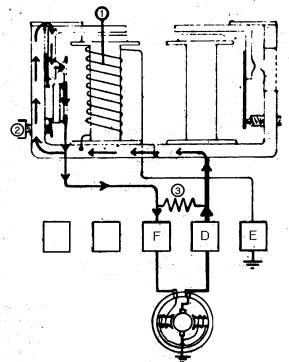
Fig. 2
In Fig. 2 we can see the circuit from generator terminal (D) to the
frame, through the regulator contacts, and back to the generator terminal (F);
this means the generator field is connected and there will be an output from
the generator. To regulate this, a shunt coil (Fig. 2-1) is wound round
the core with one end connected to the frame (dynamo potential) and the other
to earth. When current flows through this coil, magnetism tends to pull the
armature down against the spring; at a given voltage it will overcome the
spring and the O & F connection will be broken. Because the generator
output now falls, current through the shunt coil will also fall, reducing the
magnetism until spring tension closes the contacts again. This cycle is
repeated approximately 60 - 100 times per second, which gives a steady control
over generator voltage.
The controlled voltage can
easily be set to the required level by using the screw (Fig. 2-2) to adjust the spring tension. If we break the circuit
when the field current is passing
considerable arcing will take place across the regulator points, also the
generator field will be slow to collapse. To prevent this, a resistance (Fig. 2-3) is placed in parallel with
the points.
CUT-OUT
POINTS
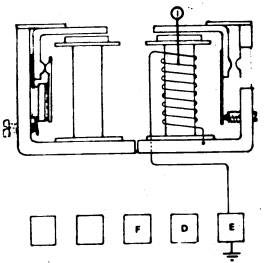
Fig. 3
The operation of the 'cut-out' (Fig. 3) is similar to that of the
regulator, except that the points are spring loaded open, and the magnetic pull
draws them together. A similar shunt Coil (Fig.
3- 1) is wound around the cut-out core with one-end connected to the frame
and the other to earth. Spring tension is set so that the points close when the
generator output is Just above nominal terminal voltage of the battery and open
again to disconnect the battery as the generator output falls.
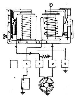
Fig. 4
Fig. 4 shows a constant
voltage control circuit where Output from the 'D' terminal goes to the
regulator frame, the cut-out points are pulled together, and current is passing
around the heavy series winding (Fig.
4 - 1) on the cut-out bobbin and on to terminal 'A' which is connected to
the battery.
The purpose of the series coil is to add strength to the shunt coil.
Once the contacts have closed, current passing to the battery along the series
winding strengthens the magnetic field and prevents the contacts 'bouncing' or
'chattering'. Also, when generator output falls below battery voltage, the
current reverses in the series winding, causing the magnetic field to collapse
quickly and open the cut-out points.
The generator voltage then builds up until it reaches the pre-set level
when the regulator points operate.
The problem that would now arise is that if the battery was in a low
state of charge, the pressure differential would be too great, and the heavy
current flow could damage the armature. To prevent this, a series coil (Fig. 5 - 1) is wound around the
regulator bobbin in the circuit from the cut-out series coil to the 'A'
terminal; this means that all the current passing from the generator to the
battery passes through these compensating turns, so adding to the magnetic
field of the shunt coil. The heavier the current, the stronger the magnetic
field and the sooner the regulator points open. This lowers the operating
voltage of the dynamo and restricts the current flow to a safe limit.
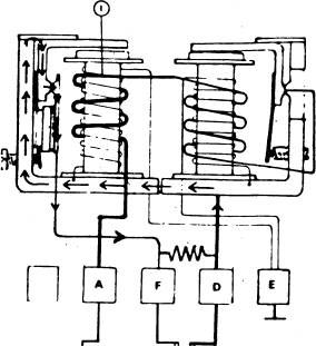
Fig. 5
As the state of charge of the battery
improves, the charging current will decrease, the series turns magnetism
decreases, and the voltage at which the contacts open will become higher, until
finally it is only limited by the shunt coil.
Any extra
load - e.g. lights, heater, wipers, etc., - must also be catered for, and extra
turns, called load turns (Fig. 6-1), may be added to the
regulator series coil and taken out to A1, which is connected to the ignition
switch, lights, and accessories fuse.
Fig. 6
Both shunt
coils consist of many turns of' fine wire, the resistance of which varies with
changes in temperature. As temperature increases, resistance increases, and
due to the reduction in current flow, magnetism will be lowered, and therefore
the voltage required to operate the contacts would increase. To counteract
this, each armature tension spring has a bi-metal strip fitted (Fig. 6- 2). these
cause the spring tension on the armature to fall as temperature rises - and so
maintain control at the specified voltage.
POSSIBLE FAULTS
Malfunction of the control box can be due to several
factors:
1. Incorrect electrical settings.
2. Oxidization of the points.
3. Incorrect air gaps.
N.B. THE REGULATOR SETTINGS SHOULD ALWAYS
BE CHECKED BEFORE DEALING WITH THE CONTACT POINTS AND
AIR GAPS.
1. REGULATOR SETTINGS
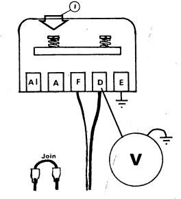
Fig. 7
Disconnect A
and A1 leads, this will disconnect the battery from the generator and take the
series windings out of circuit.
Connect a voltmeter between the regulator
frame or 'D' terminal and earth. Join the A and A1 leads to provide an ignition
feed.
Start the
engine and run up to charging speed: the voltage reading will increase until
the setting point of the regulator is reached and there should then be no
further Increase· If the voltage does not conform to specification for the
particular model, turn screw (Fig.7-1) inwards to increase the voltage, or
outwards to lower it, then re-check the reading·
CUT-OUT
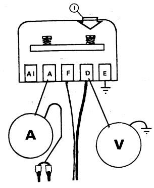
Fig.
8
We must now
check the operation of the cut-out. Leaving the voltmeter connected as before,
connect in ammeter between control box ‘A’ and the disconnected leads, Switch
on the headlamps, start engine, and slowly Increase speed. The voltage reading
will rise steadily, and when the contact points close the voltage will drop
back and then rise again. The point reached just before the drop back should be
between 12.7 and 13.3 volts.
If outside
these limits, switch off the engine, and. adjust screw (Fig. 8-1), inwards to raise the voltage,
outwards to lover it.
REVERSE CURRENT
Once the
cut-In voltage is correct, the reverse current should be checked. Leaving the
ammeter and voltmeter connected as before, and with headlamps still on, run the
engine at charging speed, ensuring that the ammeter is indicating a charge.
Watch the
ammeter carefully as you slowly reduce engine speed. The ammeter should
register a slight discharge - of approximately 2 to 5 amps before the cut-out
points open - before return to zero
CIRCUIT VOLTAGE DROP (SUPPLY LINE)
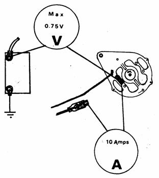
Fig. 9
We should now
check the supply line from dynamo to battery for high resistance. Remove the
'D' lead at the dynamo, and connect the ammeter into the circuit. Start and run
engine, increasing speed until ammeter indicates 10 amps. Connect voltmeter
between ‘D’ terminal of dynamo and the battery Insulated terminal, and the
voltmeter reading should not exceed 0.75 volt.
2. OXIDISATION
OF THE POINTS
It is
Important to note that the regulator points are made of tungsten, and should be
cleaned with carborundum stone or silicon carbide paper, but the cut-out
points are made of silver, and should only be cleaned with fine glass paper.
All dust should be removed, preferably with a cloth soaked in methylated
spirit.
3. AIR GAP SETTING RB. I06/2
REGULATOR
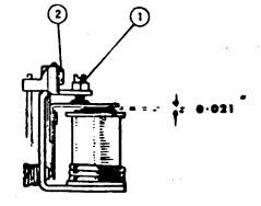
Fig.10
Unscrew
the fixed contact adjustment
Unlock
armature-securing screws
Insert 0.021" feeler gauge
between armature and core face, Press armature down squarely against the gauge
and re-tighten armature fixing screws (Fig. 10-2)
Leaving gauge in position, screw the
fixed contact down until it just touches the moving contact, and tighten
locknut.
Always
reset the voltage setting after cleaning or resetting.
CUT-OUT
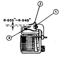
Fig. 11
Unscrew the armature securing screws
(Fig. 11-1)
Press the armature down on the core
face and re-tighten the securing screws. Bend the stop arm (Fig. 11-2)
to give a gap of 0.025" to 0.040" to the armature tongue, with the
armature held down. Release the armature and set insulated contact arm (Fig.11-3)
to give a contact "follow-through” of between 0.010” to
0.020" when armature is pressed against core face.